Alignments
EN 22 TPM5.1E LA6.
2011-Sep-02
6. Alignments
Index of this chapter:
6.1
General Alignment Conditions
6.2 Hardware Alignments
6.3 YPbPr Mode display adjustment
6.4 PC mode display adjustment
6.5 LCD Panel Flicker Adjustment
6.6 Option Settings
6.7 Serial Number Definition
Note: The Service Alignment Mode (SAM) are described in
chapter 5.
Service Modes, Error Codes, and Fault Finding.
Menu navigation is done with the CURSOR UP, DOWN, LEFT
or RIGHT keys of the remote control transmitter.
6.1 General Alignment Conditions
Perform all electrical adjustments under the following
conditions:
• Power supply voltage: 195 - 264 V
AC
, 50/ 60 ± 3 Hz.
• Connect the set to the mains via an isolation transformer
with low internal resistance.
• Allow the set to warm up for approximately 15 minutes.
• Measure voltages and waveforms in relation to correct
ground.
Caution: It is not allowed to use heatsinks as ground.
• Test probe: R
i
> 10 MΩ, C
i
< 20 pF.
• Use an isolated trimmer/screwdriver to perform
alignments.
6.2 Hardware Alignments
Not applicable.
6.3 YPbPr Mode display adjustment
6.3.1 General set-up
Equipment Requirements:
Minolta CA-110 or Equivalent Colour analyser. Quantum Data
Pattern Generator 802G, 802BT or equivalent instrument.
Input requirements:
Input Signal Type: YPbPr signal
• 1080i mode, TVBar100 pattern by 802G or 802BT.
• Select Picture mode to User mode and check the x, y data.
Input Signal Strength:
1 V
pp
for Y signal; 700 mV
pp
for Pb & Pr signal
Input Injection Point:
YPbPr (RAC jack)
6.3.2 Alignment method
Quantum Data Pattern Generator 802G or 802BT. Apply 1080i,
and the pattern TVBAR100 shown as below.
Initial Set-up:
1. Select source as “EXT3”.
2. Set Smart Picture mode as “Vivid” and off the “Dynamic
contrast/Dynamic backlight”.
3. Apply “TVBar100” pattern with colour bar pattern by signal
generator.
4. Enter factory mode menu: press numeric keys
“062596” + INFO key (FAC mode menu).
Alignment:
1. At SAM mode menu, select AUTO_COLOR item. Then
press “OK” key to adjust ADC_GAIN_R, ADC_GAIN_G,
ADC_GAIN_B and ADC_OFFSET_R, ADC_OFFSET_G,
ADC_OFFSET_B. Then store those values to NVM.
2. Apply 80% white pattern.
3. Set colour temperature to “NORMAL”.
4. At FAC mode menu, adjust the CLR TEMP R, CLR TEMP
G, CLR TEMP B values to meet “NORMAL” colour
coordinates specification below. Then store those values to
NVM (R/G/B gain value <= 128).
5. Set colour temperature to “COOL”.
6. At FAC mode menu, adjust the CLR TEMP R, CLR TEMP
G, CLR TEMP B values to meet “COOL” colour
coordinates specification below. Then store those values to
NVM (R/G/B gain value <= 128).
7. Set colour temperature to “WARM”.
8. At FAC mode menu, adjust the CLR TEMP R, CLR TEMP
G, CLR TEMP B values to meet “WARM” colour
coordinates specification below. Then store those values to
NVM (R/G/B gain value <= 128).
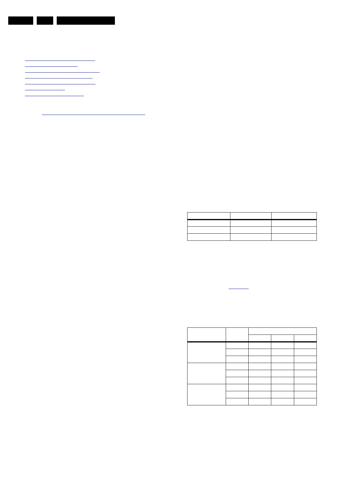
Colour temperature Normal/Warm/Cool (x, y) co-ordinates
specification:
Table 6-1 Reading with Minolta CA-210
If you do not have a colour analyser, you can use the default
values. This is the next best solution. The default values are
average values coming from production.
• Select a COLOUR TEMPERATURE (e.g. COOL,
NORMAL, or WARM).
• Set the RED, GREEN and BLUE default values according
to the values in Table 6-2
• When finished press OK on the RC, then press STORE (in
the SAM root menu) to store the aligned values to the NVM.
• Restore the initial picture settings after the alignments.
Table 6-2 White tone default settings
Caution:
• Use Minolta CA-210 for colour coordinates and luminance
check.
• Luminance > 400 cd/m
2
in the centre of the screen when
Brightness/Contrast/Video Contrast setting at 100 and
CLR_TEMP_R/CLR_TEMP_G/CLR_TEMP_B = 128 for
32"/42"/47" panels.
Picture Mode Cool Normal
Normal (9000K) 0.287 ± 0.003 0.296 ± 0.003
Cool (11000K) 0.276 ± 0.003 0.282 ± 0.003
Warm (6500K) 0.313 ± 0.003 0.329 ± 0.003
Picture mode
Screen
size
Colour temperature
Red Green Blue
Normal 32" 127 124 119
42" 127 126 113
47" 128 128 116
Cool 32" 119 114 127
42" 125 121 127
47" 120 124 128
Warm 32" 127 114 73
42" 127 118 72
47" 128 122 76