Alignments
EN 23TPM5.1E LA 6.
2011-Sep-02
6.4 PC mode display adjustment
6.4.1 Display quality adjustment
Use timing mode and use the POPO (pixel on pixel off) pattern
to adjust the clock until no stripe and adjust the phase until
clear picture (“Auto” will be done every time switching to PC
mode and mode change).
6.4.2 WHITE-D adjustment
Equipment Requirements:
Minolta CA-210 or Equivalent Colour analyser, Chroma 2250
or equivalent PC signal generator.
Input requirements:
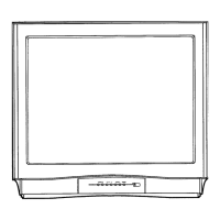
Input Signal Type: PC VGA signal, 1366 × 768/60 Hz PC mode
with “five white block” pattern.
Figure 6-1 Five white blocks pattern
Input Signal Strength:
0.7 V
p-p
linear voltage.
Input Injection Point:
PC D-SUB input.
6.4.3 Alignment method
Initial Set-up:
1. Select source as “PC”.
2. Set Contrast = 50 (Sharp) and Brightness=50 (Sharp), at
normal menu mode.
3. Apply “5 white block” pattern by VGA pattern generator,
see Figure 6-1
.
4. Enter factory mode menu: press numeric keys “062596” +
INFO key (FAC mode menu).
6.4.4 Alignment
1. At FAC mode menu, select AUTO_COLOR item. Then
press “OK” key to adjust ADC_GAIN_R, ADC_GAIN_G,
ADC_GAIN_B and ADC_OFFSET_R, ADC_OFFSET_G,
ADC_OFFSET_B. Then store those values to NVM.
6.5 LCD Panel Flicker Adjustment
6.5.1 Flicker (V-COM) adjustment
Equipment Requirements:
Chroma 2250 or equivalent PC signal generator.
Input requirements:
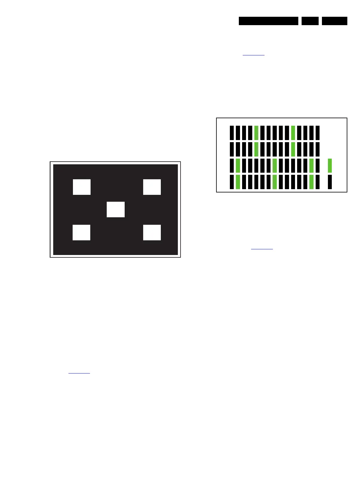
Input Signal Type: PC VGA signal or software built-in test
pattern, 1920 × 1080/60 Hz PC mode with “Pixel ON/OFF”
pattern, see Figure 6-2
.
Input Signal Strength:
0.7 V
p-p
linear voltage.
Input Injection Point:
PC D-SUB input.
6.5.2 Alignment method
Figure 6-2 1920 × 1080 @ 60 Hz, Pixel ON/OFF pattern
Initial Set-up:
1. Select source as “VGA”.
2. Apply “Pixel ON / OFF” pattern by signal generator or use
a factory cone and to enable built-in “Pixel ON / OFF”
pattern, see Figure 6-2
.
3. Enter factory mode menu: press numeric keys “062596” +
INFO key (FAC mode menu).
6.5.3 Alignment
1. At FAC mode menu, select V-COM item. Then press “OK”
key to start adjusting panel flicker. By pressing “<-” or “->”
key on RC to decrease or increase V-COM value, minimize
panel flicker.
2. Once panel flicker is minimal, press “OK” key on RC to
store V-COM value to V-COM IC’s MTP and NVM.
Caution: Please note that P Gamma IC is 100 times-write
ONLY. Make sure you get the optimum result before press
“OK” to save the V-COM data.
6.6 Option Settings
6.6.1 Introduction
The microprocessor communicates with a large number of I
2
C
ICs in the set. To ensure good communication and to make
digital diagnosis possible, the microprocessor has to know
which ICs to address. The presence/absence of these specific
ICs (or functions) is made known by the option codes.
Notes:
• After changing the option (s), save them by pressing the
“OK” button on the RC before the cursor is moved to the
left, select STORE in the SAM root menu and press “OK”
on the RC.
• The new option setting is only active after the TV is
switched “off”/“stand-by” and “on” again with the Mains
switch (the NVM is then read again).
18290_201_090330.eps
090416
18850_207_100107.eps
100107
R
Row 1
Row 2
Row 3
Row 4
127 gray
0 gray
G B R G B R G B R G B R G B