GW PL ETH/…BUS
8/46
PHOENIX CONTACT 3433_en_C
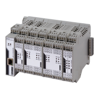
Figure 2-4 GW PL HART8-BUS/GW PL HART8-R-BUS structure
2.2.1 Connections
HART
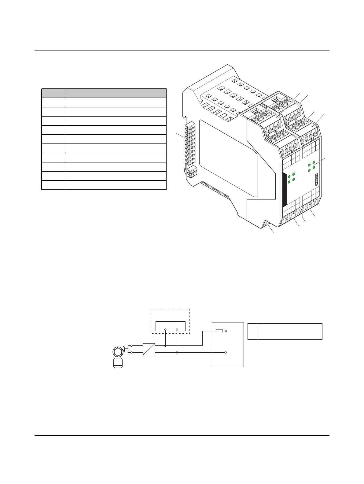
Connect the HART field devices according to Figure 2-5 to Figure 2-8. An optional isolator
or repeater power supply may be installed.
Figure 2-5 HART analog in connection
S5
H+5
S5
H-5
S6
H+6
S6
H-6
S1
H+1
S1
H-1
S2
H+2
S2
H-2
CH3
CH4 CH7 CH8
CH6
CH5
CH2
CH1
GW PL HART8-BUS
SH-
H+
S
SH-H+S
SH-
H+
S
SH-H+S
SH-
H+
SSH-
H+
S
SH-
H+
SSH-
H+
S
1111
22
2
2
5
5
55
6
6
6
6
3333 7
777
4
4
4
48
8
88
6
2
4
3
8
7
5
1
9
10
Table 2-3 GW PL HART8-BUS/GW PL HART8-R-
BUS structure
Item Function
1 Channel 1 connector
2 Channel 2 connector
3 Channel 3 connector
4 Channel 4 connector
5 Channel 5 connector
6 Channel 6 connector
7 Channel 7 connector
8 Channel 8 connector
9 Status LEDs (one per channel)
10 BUS connector
+
-
+
-
In
PLC
GW PL HART/...-BUS
4...20 mA
HART
Vcc
>250 Ω
H+ H-
A
A Optional isolator or
repeater power supply
 Loading...