Installation
3433_en_C PHOENIX CONTACT 15/46
3 Installation
All GW PL ... devices are installed on an NS 35 DIN rail. An internal communication bus
within the rail allows the head station to power and communicate with the various expansion
modules. Up to five expansion modules of different types can be attached and powered
from one head station.
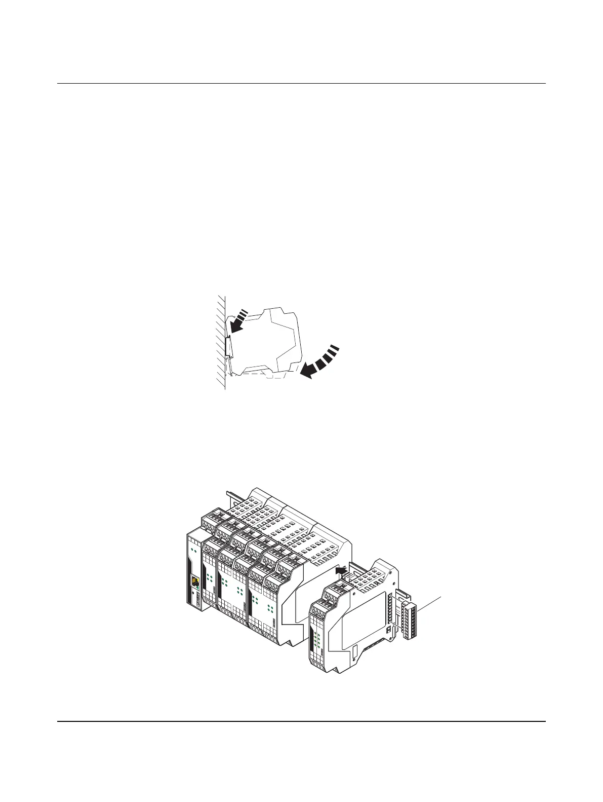
3.1 Mounting
Installation
1. Hook the GW PL ETH/…BUS head station over the top edge of the DIN rail (A) and
rotate down until it snaps onto the bottom edge of the DIN rail (B).
Figure 3-1 Mounting
2. Repeat step 1 for all expansion modules, ensuring that they are to the right of the
GW PL ETH/…BUS.
3. Slide the expansion modules, one at a time, to the left until the bus connectors mate.
Repeat for each module.
Figure 3-2 Module and terminator plug installation
A
B
2
4
V
OV
ST
PWR
GW PL ETH/UNI-BUS
24V 0V
S
2
H
2
+
H
2–
S
2
S
1
H
1
+
H1–
S
1
GW PL HART4-BUS
S
SS
S
S
SS
S
H
+H–
H
+
H–
H
+
H–
H
+
H–
CH
1
CH2
C
H3 CH4
11
1
1
22
2
2
33
3
3
4
4
44
S
6H
6
+
H
6–
S
6
S
5
H
5
+
H
5
–
S
5
S
2
H
2
+
H
2
–
S
2
S
1H
1+
H
1
–
S
1
S
8
8
8
84
4
4
4
7
7
7
73
33
3
55
5
5
66662
222
1111
H
+H– S S H+H– S
S
H
+H– S S H+H– S
S
H
+H– S
SH+
H– S
S
H
+H– S
SH+
H– S
GW PL HART8+AI-BUS
CH
1CH2 CH5
CH6
CH8
CH
7
CH4
CH
3
S
6
H
6
+
H
6–
S
6
S
5
H
5
+
H
5
–
S
5
S
2
H
2+
H
2
–
S
2
S
1
H
1
+H
1
–
S
1
C
H
3
CH4
CH7 CH8
CH6CH5
C
H
2C
H
1
GW PL HART8-BUS
S
H–H+S
S
H–
H+S
S
H–H+S
SH–H+S
S
H–H+SSH–
H+S
S
H–H+
S
S
H–H+S
111
1
2
2
22
5
5
5
5
6
6
6
6
3
3
3
37
7
7
7
4
4
4
4
8
8
8
8
2
+
2
–
A
2
B2
1
+
1
–A
1
B1
O
UT
IN
CH
1
CH
2
C
H
3
C
H
4
B
B
B
A
A
A
–
–
–
+
+
+
BA
–+
GW PL DIO4-BUS
1
1
1
1
2
2
2
2
3
3
3
3
4
4
4
4
1
 Loading...