onlinecomponents.com
IBSL SYS PRO UM E
1-24 6057AC01
1.8.3 Connecting the Installation Remote Bus
(BK Module With IP 65/IP 67 Protection)
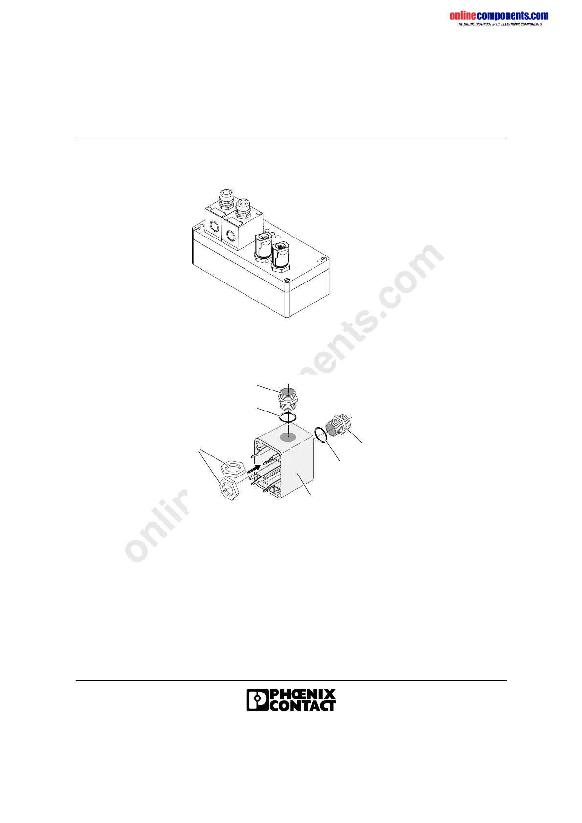
Figure 1-19 Example of a BK module with IP 65/IP 67 protection
Preparing the Connector Hood
Figure 1-20 Fitting the threaded joints
• Remove the two screws of the connector hood and remove the
connector hood.
• Use a screwdriver to break the cable openings out of the connector
hood (1).
• Push the O-ring (3) onto the threaded joint (4).
• Place the hexagonal metal nut (2) of the PG-threaded joint in the
recess or in the slot of the connector hood (1).
• Tighten the cable gland until the end by turning the threaded joint (4)
with a wrench (17 mm [0.669 in.]).
5 7 9 6 0 4 0 1
1
2
4
3
3
4
5091A004
 Loading...