onlinecomponents.com
INTERBUS Loop
6057AC01 1-27
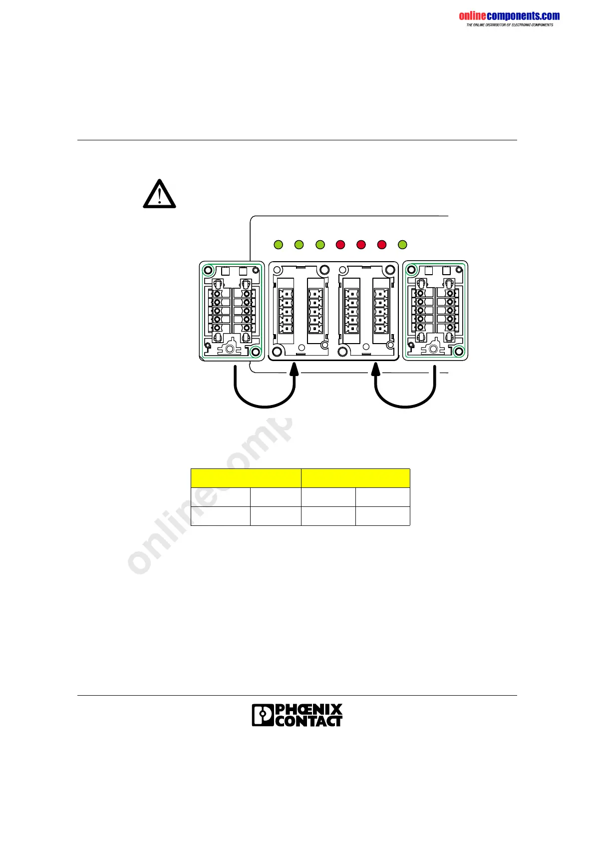
Placing the Connector Hoods
Danger of damage to the module electronics!
Do not mix up the terminals, as this may damage the electronics.
Figure 1-24 Placing the connector hoods
• Push the shielding contact into the connector hood using the rails
provided for it.
• Snap the wired MINI-COMBICON connectors according to the color
coding onto the locking clips.
• Fasten the connector hoods with the supplied screws.
Table 1-2 Color assignment of the MINI-COMBICON connector
INTERBUS IN INTERBUS OUT
Green GN Gray GY
Black BK Blue BU
G N
B K
G Y
B U
B
A
D
C
E
[
G N
B K
B U
G Y
[
G
F
J
H
K
B
A
D
C
E
[
[
G
F
J
H
K
- U
S 1
+ U
S 1
- U
S 1
+ U
S 1
U
L
L
- U
S 1
+ U
S 1
U
L
L
- U
S 1
+ U
S 1
U L
R C B A E L D R D
U
S L
- U
S 2
+ U
S 2
- U
S 2
+ U
S 2
5 1 0 9 B 9 0 8
 Loading...