onlinecomponents.com
IBSL SYS PRO UM E
1-26 6057AC01
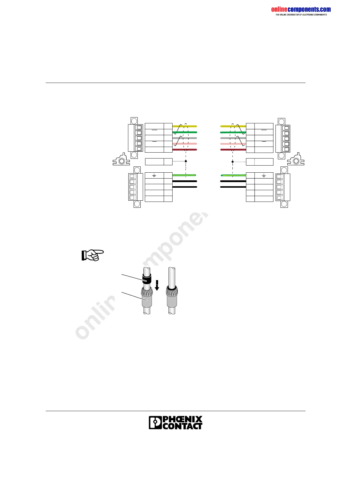
Wiring MINI-COMBICON Connectors
Figure 1-22 MINI-COMBICON pin assignment
Mounting Strain Relief
Ensure the tightness of the opening to guarantee IP 65 protection of the
module.
Figure 1-23 Strain relief and flexible ring
• Push the flexible ring (6) into the strain relief (5).
• Push the strain relief (5) into the threaded joint (4) (see Figure 1-21).
• Pull the cable back so that the outer cable sheath is still visible from the
inside of the connector hood.
• Fasten the cap (7) onto the threaded joint (4) by turning the cap with a
wrench (17 mm [0.669 in.]) (see Figure 1-21).
y e l l o w / g r e e n
b l a c k 1
b l a c k 2
g r a y
b l u e
KJF HG
[
U
L
L
- U
S 1
+ U
S 1
p i n k
y e l l o w
g r a y
b r o w n
6 0 5 7 A 0 2 2
w e i t e r f ü h r e n d e r F e r n b u s
O u t g o i n g i n s t a l l a t i o n
r e m o t e b u s
a n k o m m e n d e r F e r n b u s
I n c o m i n g i n s t a l l a t i o n
r e m o t e b u s
g r e e n
b l a c k
[
+ U
S 1
- U
S 1
+ U
S 2
- U
S 2
[
+
U
S 1
- U
S 1
0 V
+ 2 4 V
B D CA E
S h i e l d
[
S h i e l d[
D O
D I
C O M
B
A
D
C
E
D I
D O
D O
D I
C O M
G
F
J
H
K
D I
D O
g r e e n
[
+
U
S 1
- U
S 1
R B S T
+ 5 V
0 V
+ 2 4 V
L
U
L
6
5
6 0 5 7 A 0 2 3
 Loading...