onlinecomponents.com
INTERBUS Loop
6057AC01 1-35
To avoid mixing up IN and OUT connections of the installation local bus,
the splice ring keying for the incoming installation local bus (IN) is circular
and the splice ring keying for the outgoing installation local bus (OUT) is
square.
When the actuator supply is connected, mixing up IN and OUT will have no
effect.
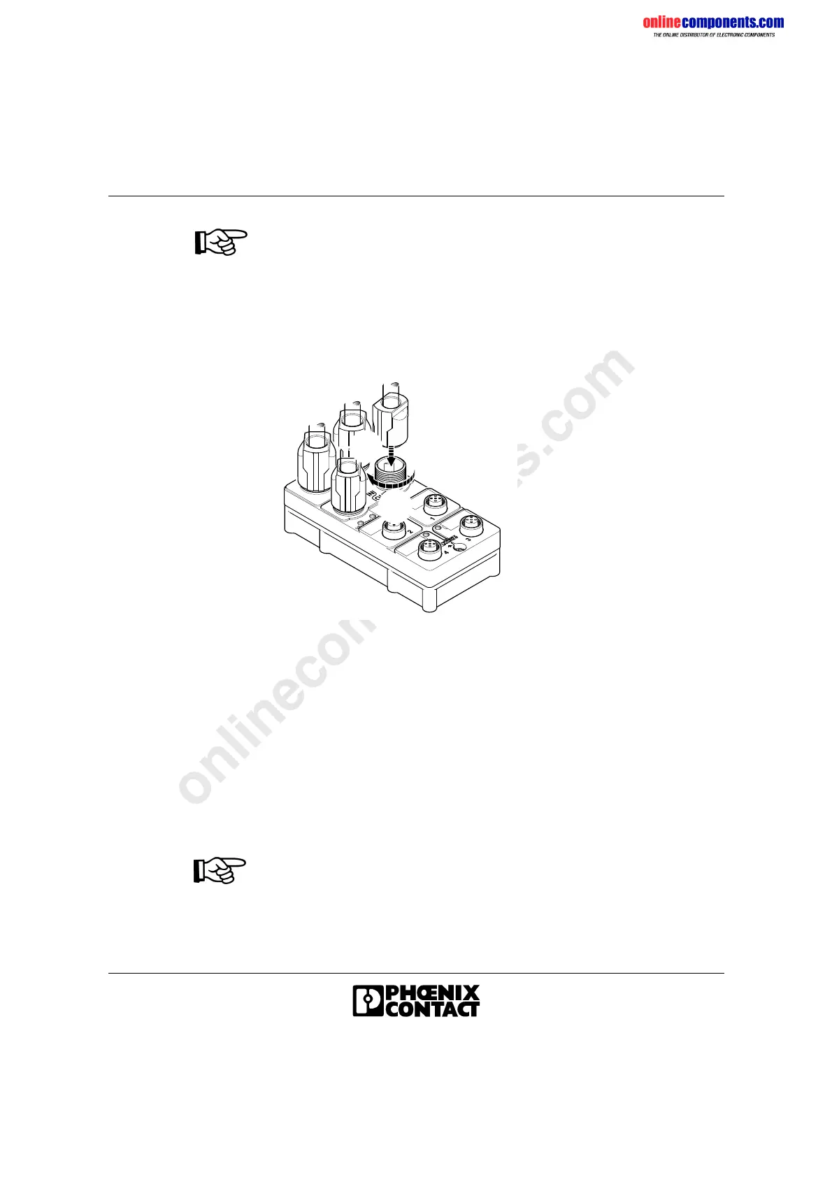
Mounting QUICKON
Figure 1-29 Mounting the connecting cable
• Turn the assembled cable until the coding tabs fit exactly into the
guideways.
• Tighten the threaded joint by turning the cap nut.
The insulation is cut open and the electrical contact is established
(QUICKON connection method).
Cover unused
connections
• Cover the unused connections for the actuator supply with filler plugs
and screw down the cap nut to ensure IP 65/IP 67 protection.
• Cover unused sensor/actuator sockets with protective caps
(accessories) to ensure IP 65/IP 67 protection.
After removing a QUICKON connection you must cut off the slit open wires
and repeat the assembly steps.
5 7 9 6 0 4 1 1
A
B
 Loading...