7
DMX15012501
REAR PANEL DESCRIPTION
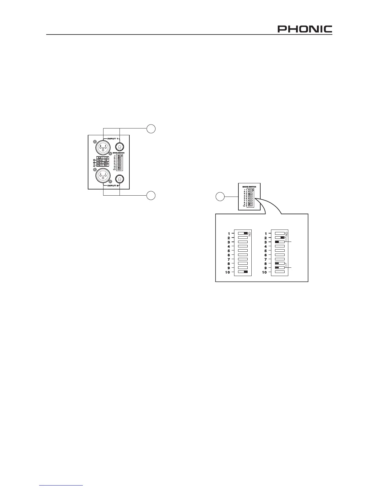
6. Input Connectors
The power amplier offers XLR and TRS input con-
nectors for your convenience. The DMX amplier
can accept any line-level signal. When in Parallel
mode, the input from channel 1 is doubled over and
sent through to the channel 2 output, therefore rend-
ing the channel 2 input connection useless.
7. Mode Switches
LIMITER ON/OFF
The DIP switched labeled 1 and 10 will allow you to
activate the peak limiter circuit built into the power
amplier. This function will reduce distortion and pro-
tect speakers. To activate the built-in limiter on chan-
nel 1, move the number 1 DIP switch to the right; to
activate the built-in limiter on channel 2, move the
number 10 DIP switch to the right.
LOW CUT FILTER
DIP switches 2 and 3 can activate a low cut lter
on channel 1; DIP switches 8 and 9 can activate an
LCF on channel 2. A low cut lter will roll off signals
below either 30 Hz or 50 Hz to improve sub bass
performance by limiting sub bass cone motion, as
well as making more power available for the speak-
ers’ rated frequency range. To activate the low cut
lter on channel 1, DIP switch 3 should be moved
to the left position. DIP switch 2 decides the cut off
frequency of the LCF, 50Hz (left) or 30Hz (right). To
activate the low cut lter on channel 2, DIP switch 8
should be moved to the left position, and DIP switch
9 determines the cut off frequency.
6
6