Do you have a question about the Phrozen SONIC MINI 4K and is the answer not in the manual?
Remove the resin vat and any objects from the machine's platform before calibration.
Attach the building plate, align it with pins, and screw it firmly to the printer.
Use an Allen wrench to loosen all four screws counterclockwise, ensuring plate mobility.
Pull the building plate down until the screws are completely extended.
Lay a piece of A4 paper (0.07-0.10 mm) flat on the LCD screen for leveling.
Access TOOLS > Z CALIB on the touch panel to begin the calibration process.
Once the plate touches down, press down firmly on its sides.
Tighten all four screws clockwise in a cross pattern while pressing the plate.
Tug the paper at corners to check for tight resistance, indicating correct calibration.
Click DONE on the touch panel and wait for the building plate to retract.
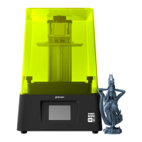
This document outlines the Z-axis calibration process for the Phrozen Sonic Mini 4K 3D printer, a crucial procedure to ensure successful 3D printing by properly leveling the building plate to the LCD screen. This calibration guarantees that printed models will adhere correctly to the building plate, preventing print failures.
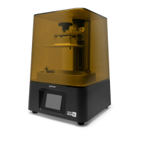
The Phrozen Sonic Mini 4K is a 3D printer designed for additive manufacturing. Its primary function is to create three-dimensional objects from digital designs by curing liquid resin layer by layer using an LCD screen. The Z-axis calibration is a fundamental setup step that ensures the precise vertical positioning and parallelism of the building plate relative to the LCD screen, which is essential for accurate and reliable print adhesion and quality. Without proper calibration, prints may detach from the building plate, warp, or fail entirely. The printer utilizes a building plate where the 3D object is formed, and a resin vat that holds the liquid resin. The LCD screen beneath the resin vat selectively cures the resin, solidifying each layer of the print. The Z-axis mechanism moves the building plate up and down, allowing for the sequential curing of layers.
The calibration process is initiated through the printer's touch panel, providing an intuitive user interface for controlling the device. The steps are clearly delineated, guiding the user through each stage of preparation and adjustment.
Removing the Resin Vat: Before starting the calibration, the resin vat must be removed from the machine's platform. This step is critical to prevent damage to the vat or the LCD screen during the calibration process and to ensure that no obstructions interfere with the building plate's movement. Users must ensure no other objects are present on the platform.
Installing the Building Plate: The building plate is then attached to the printer. This involves aligning the building plate knob with specific pins on the printer and screwing it into place. It's crucial to tighten the building plate securely while ensuring it does not shift, as any misalignment at this stage can compromise the accuracy of the calibration.
Loosening the Screws: To allow for adjustment, four screws on the sides of the building plate need to be loosened. An Allen wrench is used for this purpose, turning the screws in a counterclockwise direction. After loosening, the user should verify that the plate is loose and movable, indicating it's ready for adjustment.
Pulling the Building Plate Down: The building plate is then manually pulled downwards until the screws are completely extended. This ensures that the plate is at its lowest possible position relative to the Z-axis mechanism, providing the maximum range for calibration.
Placing a Piece of Paper on the LCD: A standard A4 piece of paper, approximately 0.07-0.10 mm thick, is placed flat on the LCD screen. This paper acts as a spacer and a tactile indicator for proper leveling. It helps the user feel the correct pressure between the building plate and the LCD screen.
Initiating Calibration via Settings: The calibration process is formally started through the printer's touch panel. Users navigate to "TOOLS" and then select "Z CALIB." After clicking "NEXT," the building plate automatically extends downwards towards the LCD screen. This automated movement ensures a consistent starting point for the manual adjustment. The user waits 1-2 minutes for the plate to reach the LCD screen.
Applying Pressure on the Building Plate: Once the building plate makes contact with the paper on the LCD, the user manually applies firm pressure on the sides of the building plate. While maintaining this pressure, the user pulls on the piece of paper. The goal is to achieve a slight resistance when pulling the paper, indicating that the building plate is lying tight against it without being overly clamped or too loose. This step is critical for achieving the correct gap between the building plate and the LCD.
Tightening the Screws in a Cross Pattern: With the correct pressure applied and the building plate properly positioned, the four screws on the sides of the building plate are tightened. This must be done in a specific cross pattern (e.g., top-right, lower-left, top-left, lower-right) to ensure even tightening and prevent the plate from shifting or becoming uneven. While tightening, the user should continue to press down on the building plate with the other hand to maintain its position.
Double-Checking Z-axis Calibration: After tightening, the user performs a final check by tugging on all four corners of the A4 paper. If the paper feels tight and offers resistance, the calibration is successful. If the paper is still loose, the entire Z-axis calibration process must be repeated. In cases where the paper remains loose after several attempts, the manual suggests performing the calibration directly on the resin vat, noting that the FEP (Fluorinated Ethylene Propylene) film in the vat has a thickness of approximately 0.14-0.15 mm, which might be a more accurate reference in some scenarios.
Completing the Calibration: Once the calibration is confirmed to be successful, the user clicks "DONE" on the touch panel. The building plate then retracts to its home position. The A4 paper is removed, and the printer is now ready for 3D printing.
The Z-axis calibration itself is a maintenance procedure that ensures the printer's optimal performance. Regular calibration, especially after moving the printer or if print adhesion issues arise, is crucial for maintaining print quality. The process is designed to be user-friendly, allowing operators to perform this essential maintenance without specialized tools beyond an Allen wrench, which is typically supplied with the printer. The emphasis on checking the tightness of the paper and repeating the process if necessary highlights a self-correcting aspect of the maintenance, empowering users to troubleshoot and ensure proper setup. The alternative method of calibrating directly on the resin vat (considering the FEP thickness) provides a contingency for more challenging calibration scenarios, demonstrating a robust approach to maintaining print accuracy.
| XY Resolution | 35 microns |
|---|---|
| Layer Thickness | 0.01-0.30 mm |
| Connectivity | USB |
| Resin Compatibility | 405nm UV resin |
| Operating System | Phrozen OS |
| Slicer Software | ChiTuBox |
| Technology | LCD |
| Build Volume | 135 x 75 x 130 mm |
| Light Source | ParaLED Matrix 2.0 |
| LCD Resolution | 3840 x 2160 pixels |
| Z Resolution | 0.00125 mm |
| Printing Speed | Up to 80 mm/hr |