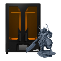
This document outlines the procedure for replacing the Z-axis screw on a Phrozen Sonic Mini 8K S 3D printer. The Z-axis screw is a critical component for the vertical movement of the build platform, and its proper functioning is essential for high-quality prints. Over time, dust and debris can accumulate, leading to clogs in the Z-axis screw and its associated bearing sleeve. This can manifest as layer lines in prints or even a complete malfunction of the Z-axis, necessitating replacement.
The replacement process is divided into two main sections: removing the old Z-axis and installing the new Z-axis. Each step is clearly described and, in some cases, accompanied by illustrative images to guide the user through the process.
Removing the Old Z-axis:
The initial steps focus on preparing the printer for the replacement.
- Power Disconnection: The first and most crucial step is to ensure the printer is turned off and disconnected from the power supply. This is a fundamental safety precaution to prevent electrical hazards during the maintenance procedure.
- Component Removal: The next steps involve removing external components to gain access to the internal mechanisms. This includes taking off the cover lid, the building plate, and the resin vat. These components are designed for easy removal, allowing for routine maintenance and cleaning.
- Printer Positioning: To facilitate access to the bottom case, the printer needs to be carefully laid down on a flat surface. This stable positioning is important for safely working on the device without causing damage or instability.
- Bottom Case Access: The bottom case is secured by four screws. These screws need to be loosened to open the case, revealing the internal electronics and mechanical components. The image provided clearly indicates the location of these screws, ensuring the user can identify them easily.
- Connector Disconnection (Bottom Case): Once the bottom case is open, several connectors need to be detached. Specifically, the LED connector and the fan connector must be unplugged from the mainboard. This allows the bottom case to be set aside, providing unobstructed access to the printer's interior. The image highlights these connectors, making their identification straightforward.
- LCD Ribbon Cable Disconnection: The LCD ribbon cable is a delicate component that connects the LCD screen to the mainboard. To disconnect it, the cable clip must be opened, and the cable carefully detached. The provided image uses numbered indicators to show the exact location of the cable clip and the detachment point, emphasizing the need for careful handling to avoid damage.
- Motor Connector Disconnection: The motor connector, which supplies power and control signals to the Z-axis motor, also needs to be unplugged. This step isolates the motor from the mainboard, preparing it for removal. The image clearly points out this connector.
- Platform Screw Loosening: The platform, which holds the build plate, is attached to the motor via two screws. These screws must be loosened to separate the platform from the motor assembly. The image shows the location of these screws on the platform, ensuring the user targets the correct fasteners.
- Z-axis Loosening: The Z-axis screw itself needs to be unscrewed from the bearing sleeve. This is done by turning the Z-axis counterclockwise while holding the T-plate with the other hand. This action gradually loosens the Z-axis, allowing it to be removed.
- Z-axis Removal: Finally, once loosened, the old Z-axis can be carefully taken out of the printer. This completes the removal phase, preparing the printer for the installation of the new Z-axis.
Installation of the New Z-axis:
The installation process essentially reverses the removal steps, ensuring all components are reassembled correctly.
- New Z-axis Positioning: The new Z-axis is first placed into its correct position inside the printer. This involves aligning it with the bearing sleeve and the motor assembly.
- Z-axis Tightening: The new Z-axis is then screwed into the bearing sleeve by turning it clockwise. This action secures the Z-axis in place and ensures smooth vertical movement.
- Platform Screw Tightening: The two screws on the platform that attach it to the motor are tightened. This re-establishes the connection between the platform and the Z-axis motor, ensuring the build plate moves in sync with the Z-axis.
- Motor and LCD Cable Reconnection: The motor connector and the LCD ribbon cable are reattached to their respective ports on the mainboard. It is crucial to ensure these connections are secure and correctly oriented to restore power and communication.
- LED and Fan Cable Reconnection: The LED connector and the fan connector are reattached to the mainboard. These connections are vital for the printer's lighting and cooling systems.
- Bottom Case Installation: The bottom case is then reinstalled and secured with its four screws. This protects the internal electronics and completes the printer's enclosure.
- Printer Upright Positioning: Finally, the printer is turned upright, ready for operation.
Maintenance Features:
This guide highlights a key maintenance feature of the Phrozen Sonic Mini 8K S: the ability to replace critical mechanical components like the Z-axis screw. This modular design approach allows users to perform repairs and extend the lifespan of their printer, rather than requiring a complete unit replacement for a single component failure. The detailed, step-by-step instructions, coupled with visual aids, make this a user-friendly maintenance task, even for those with limited technical experience. The emphasis on careful handling of delicate components like the LCD ribbon cable underscores the importance of precision in printer maintenance. Regular inspection for dust and debris, as implied by the reason for replacement, is also a crucial aspect of preventative maintenance for 3D printers.