- 3 -
Verdrahtung
117588491
Beachten Sie:
` Angaben im Abschnitt „Technische Daten“
unbedingt einhalten.
` Die Ausgänge 13 - 14, 23 - 24, 33 - 34 sind
Sicherheitskontakte, der Ausgang 41 - 42 ist
ein Hilfskontakt (z. B. für Anzeige).
` Vor die Ausgangskontakte eine Sicherung
(s. techn. Daten) schalten, um das
Verschweißen der Kontakte zu verhindern.
` Berechnung der max. Leitungslänge I
max
im
Eingangskreis:
R
lmax
= max. Gesamtleitungswiderstand
(s. techn. Daten)
R
l
/ km = Leitungswiderstand/km
` Leitungsmaterial aus Kupferdraht mit einer
Temperaturbeständigkeit von 60/75 °C
verwenden.
` Sorgen Sie an allen Ausgangskontakten bei
kapazitiven und induktiven Lasten für eine
ausreichende Schutzbeschaltung.
1232919051
` Sorgen Sie beim Anschluss von magnetisch
wirkenden, auf Reedkontakten basierenden
Näherungsschaltern dafür, dass der max.
Einschaltspitzenstrom (am Eingangskreis)
den Näherungsschalter nicht überlastet.
1378293899
` Das Netzteil muss den Vorschriften für
Funktionskleinspannungen mit sicherer
elektrischer Trennung (SELV, PELV) nach
VDE 0100, Teil 410 entsprechen.
1378295691
Wichtig für Querschlusserkennung:
Da diese Funktion nicht einfehlersicher ist, wird
sie von Pilz während der Endkontrolle geprüft.
Wenn Gefahr besteht, dass Sie die
Leitungslängen überschreiten, empfehlen wir
folgende Prüfung nach der Installation des
Geräts:
1. Gerät betriebsbereit (Ausgangskontakte
geschlossen)
2. Die Testklemmen S12, S22 zur
Querschlussprüfung kurzschließen.
3. Die Sicherung im Gerät muss auslösen und
die Ausgangskontakte öffnen.
Leitungslängen in der Größenordnung der
Maximallänge können das Auslösen der
Sicherung um bis zu 2 Minuten verzögern.
4. Sicherung wieder zurücksetzen: den
Kurzschluss entfernen und die
Versorgungsspannung für ca. 1 Minute
abschalten.
Wiring
Please note:
` Information given in the “Technical details”
must be followed.
` Outputs 13 - 14, 23 - 24, 33 - 34 are safety
contacts, output 41 - 42 is an auxiliary
contact (e.g. for display).
` To prevent contact welding, a fuse should be
connected before the output contacts (see
technical details).
` Calculation of the max. cable runs l
max
in the
input circuit:
R
lmax
= max. overall cable resistance (see
technical details)
R
l
/km = cable resistance/km
` Use copper wire that can withstand 60/75 °C.
` Sufficient fuse protection must be provided
on all output contacts with capacitive and
inductive loads.
` When connecting magnetically operated,
reed proximity switches, ensure that the
max. peak inrush current (on the input circuit)
does not overload the proximity switch.
` The power supply must comply with the
regulations for extra low voltages with safe
electrical separation (SELV, PELV) in
accordance with VDE 0100, Part 410.
Important for detection of shorts across
contacts:
As this function for detecting shorts across
contacts is not failsafe, it is tested by Pilz during
the final control check. If there is a danger of
exceeding the cable runs, we recommend the
following test after the installation of the device:
1. Unit ready for operation (output contacts
closed)
2. Short circuit the test terminals S12, S22 for
detecting shorts across the inputs.
3. The unit's fuse must be triggered and the
output contacts must open. Cable lengths in
the scale of the maximum length can delay
the fuse triggering for up to 2 minutes.
4. Reset the fuse: remove the short circuit and
switch off the supply voltage for approx. 1
minute.
配線
注意事項 :
`「技術データ」に記載されている情報に従ってくだ
さい。
` 出力 13 ~ 14、23 ~ 24、33 ~ 34 は安全接点、出力
41 ~ 42 は補助接点 ( ディスプレイ用など ) です。
` 接点の溶着を防ぐために、出力接点の前に必ず
ヒューズを接続してください
(「技術データ」を参照 )。
` 入力回路の最大ケーブル長 l
max
は、以下の計算式で
求められます
:
R
lmax
= ケーブル全体の最大抵抗値
(
「技術データ」を参照 )
R
l
/km = ケーブル抵抗値 /km
` 60/75 ℃の耐熱性を持つ銅線を使用してください。
` 容量性、誘導負荷のある接点を保護するため、出力
回路にはヒューズを取り付けてください。
` 磁気動作式のリード近接スイッチを接続する場合
は、入力回路の最大ピーク突入電流が近接スイッチ
の許容電流を超えないことを確認してください。
` 電源は、VDE 0100, Part 410 に準拠した安全分離
に関する低電圧指令
(SELV、PELV) に適合する必
要があります。
短絡検出に関する重要事項 :
短絡を検出するためのこの機能はフェイルセーフで
ないため、最終制御チェック時にピルツによってテス
トされています。ケーブル長が許容値を超えている可
能性がある場合は、装置の設置後に次のテストを実施
することをお勧めします。
1. ユニットを動作可能な状態にします (出力接点閉)。
2. テスト端子 S12、S22 を短絡し、入力間の短絡を
検出します。
3. ユニットのヒューズが作動して、出力接点が開く必
要があります。ケーブル長が最大長に近い場合、
ヒューズが作動するまでに最大で
2分の遅れが発生
することがあります。
4. ヒューズをリセットします。短絡を取り除き、電源を
約
1 分間オフにします。
Betriebsbereitschaft herstellen Preparing for operation
運転の準備
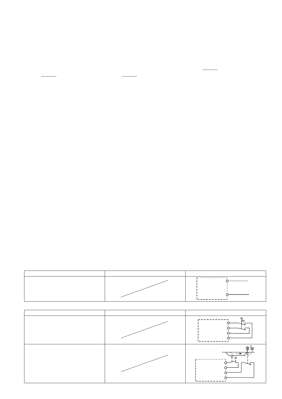
Anschluss Connection
接続
` Versorgungsspannung ` Supply voltage
` 供給電圧
Versorgungsspannung/power supply/ 電源
AC DC
` Eingangskreis ` Input circuit
` 入力回路
Eingangskreis/input circuit/ 入力回路 Einkanalig/single-channel/1 チャンネル Zweikanalig/dual-channel/2 チャンネル
Not-Halt
mit Querschlusserkennung/
E-STOP
with detection of shorts across contacts/
非常停止
短絡検出あり
Schutztür
mit Querschlusserkennung/
safety gate
with detection of shorts across contacts/
安全扉
短絡検出あり
R
lmax
R
l
/ km
I
max
=
R
lmax
R
l
/ km
I
max
=
R
lmax
R
l
/ km
I
max
=
A1
L+
A2
L-
S1
S22
S21
S12
S11
S1
S2
S12
S11
S22
S21
 Loading...