Do you have a question about the Pilz PNOZ c1 and is the answer not in the manual?
Specifies the validity period of the product documentation.
Provides guidance on how to use the manual for installation and commission.
Explains the meaning of important symbols used in the manual.
Defines the proper applications and limitations of the safety relay.
Covers safety regulations and compliance requirements for the product.
Explains the need for a safety assessment in accordance with the Machinery Directive.
Specifies that only competent personnel should handle the product.
Details the types of relay outputs available, e.g., safety and auxiliary contacts.
Lists the types of devices that can be connected to the unit.
Details the relay's redundancy, self-monitoring, and fault tolerance for safety.
Presents the block diagram and terminal layout for wiring and setup.
Explains how the unit operates based on power and input circuit status.
Describes automatic/manual start modes and methods to increase contact availability.
Details requirements for installing the unit in a control cabinet and on a DIN rail.
Provides essential information on output usage, fuse protection, EMC, and power supply.
Step-by-step guide for connecting cables using crimp connectors.
Instructions for connecting cables without using crimp connectors.
Procedure for safely disconnecting cables from the terminal points.
Diagrams illustrating wiring for supply voltage, input circuits, and start/feedback loops.
Outlines mandatory checks for safety contacts and functions after installation and changes.
Explains the meaning of the POWER, CH.1, and CH.2 LEDs for operational status.
Describes diagnosis and remedy for when all LEDs are off.
Describes diagnosis and remedy for power LED being off.
Addresses issues related to contact welding and reactivation.
Provides the physical dimensions of the PNOZ c1 unit in millimeters.
Lists the certifications obtained by the product.
Details the electrical specifications including voltage, current, and power.
Provides specifications for the input circuits, including voltage and current.
Details the number and type of output contacts and their current ratings.
Specifies utilization categories for safety contacts under AC and DC loads.
Specifies utilization categories for auxiliary contacts under AC and DC loads.
Details UL-approved utilization categories for voltage and current.
Specifies fuse protection requirements for safety and auxiliary contacts.
Lists typical and maximum switch-on delay times for various start modes.
Provides delay times for de-energisation under different fault conditions.
Specifies the recovery time after E-STOP or power failure.
Details climatic conditions, humidity, and EMC standards for operation.
Specifies airgap creepage, overvoltage category, pollution degree, and insulation voltage.
Details the protection type, housing, and terminal specifications.
Covers mounting position, mechanical life, material, and connection types.
Lists the final dimensions and weight of the unit.
Presents safety characteristic data (PL, SIL, PFH, TM) for safety contacts.
Explains the relationship between SIL CL, SIL, and mission time (TM).
Clarifies that unit SIL/PL values differ from safety function values and recommends PAScal tool.
Emphasizes considering service life graphs for safety-related data validity.
Explains PFH value dependency on switch frequency and load, and its fallback usage.
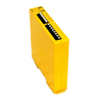
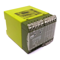
Provides product type, features, terminals, and order number.
States compliance with the Machinery Directive and provides information on where to find the full declaration.