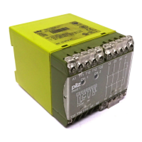
PNOZ c1
Operating Manual PNOZ c1
22197-EN-06
| 8
} Dual-channel operation with detection of shorts across contacts: redundant input circuit,
detects
– earth faults in the start and input circuit,
– shorts between contacts in the input circuit.
} Automatic start: Unit is active once the input circuit has been closed.
} Manual start Unit is active once the input circuit is closed and then the start circuit is
closed.
} Increase in the number of available contacts by connecting contact expandsion modules
or external contactors/relays.
Installation
} The unit should be installed in a control cabinet with a protection type of at least IP54.
} Use the notch on the rear of the unit to attach it to a DIN rail.
} Ensure the unit is mounted securely on a vertical DIN rail (35 mm) by using a fixing ele-
ment (e.g. retaining bracket or an end angle).
Wiring
Please note:
} Information given in the "Technical details" must be followed.
} Outputs 13-14, 23-24, 33-34 are safety contacts; output 41-42 is an auxiliary contact (e.g.
for display).
} Auxiliary contact 41-42 shouldnot be used for safety circuits!
} To prevent contact welding, a fuse should be connected before the output contacts (see
see technical details [ 14]).
} Calculation of the max. cable length l
max
in the input circuit:
R
lmax
= max. overall cable resistance (see see technical details [ 14])
R
l
/ km = cable resistance/km
} Use copper wiring with a temperature stability of 60/75 °C.
} To prevent EMC interferences (particularly common-mode interferences) the measures
described in EN60204-1 must be executed. This includes the separate routing of cables
of the control circuits (input, start and feedback loop) from other cables for energy trans-
mission or the shielding of cables, for example.
} Sufficient fuse protection must be provided on all output contacts with capacitive and in-
ductive loads.
} Do not switch low currents using contacts that have been used previously with high cur-
rents.
} When connecting magnetically operated, reed proximity switches, ensure that the max.
peak inrush current (on the input circuit) does not overload the proximity switch.
} The power supply must comply with the regulations for extra low voltages with protective
electrical separation (SELV, PELV) in accordance with VDE 0100, Part 410.
 Loading...