PNOZ c1
Operating Manual PNOZ c1
22197-EN-06
| 7
} LED for:
– Supply voltage
– Switch status channel 1
– Switch status channel 2
Safety features
The relay meets the following safety requirements:
} The circuit is redundant with built-in self-monitoring.
} The safety function remains effective in the case of a component failure.
} The correct opening and closing of the safety function relays is tested automatically in
each on-off cycle.
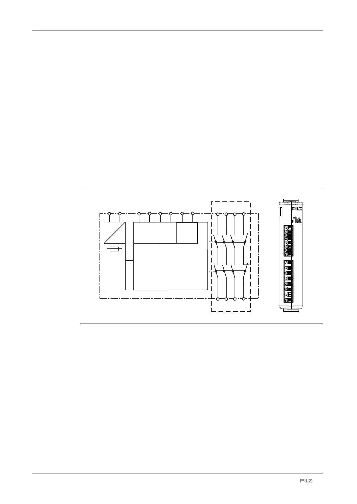
Block diagram/terminal configuration
InputInput
A1 A2 S21 S22
=
Power
Start
S11 S12
=
K1
K2
13
23 33
24 34
14
41
42
*
S33 S34
14
24
34
42
41
33
23
13
S34
S33
S22
S21
S12
S11
A2
A1
PNOZ c1
Ch. 1
Power
Ch. 2
* Insulation from non-marked area: Safe separation (overvoltage category III),
Insulation between relay contacts: basic insulation (overvoltage category III), safe separa-
tion (overvoltage category II)
Function description
When the supply voltage is supplied, the "POWER" LED illuminates. The unit is ready for
operation when the start circuit is closed.
} Input circuits closed (e.g. the E-STOP button is not pressed): The safety contacts are
closed and the auxiliary contact is open.
} Input circuit open (e.g. E-STOP operated): The safety contacts are open and the auxiliary
contact is closed.
 Loading...