- 5 -
• Stellen Sie die Starteigenschaften durch
Verdrahten des Startkreises ein.
➀ "NOT-AUS" symbolisiert Öffnerkontakt
des Auslöseelements
Eingangskreis
Input circuit
Circuit d’entrée
Einkanalig
Single-channel
Commande par 1 canal
Zweikanalig
Dual-channel
Commande par 2 canaux
ohne Querschlusserkennung
without detection of shorts across contacts
sans détection des court-circuits
mit Querschlusserkennung
with detection of shorts across contacts
avec détection des court-circuits
S12
S22
S1
A1
Y4
S11
S22
S21
S11
S1
S12
Y4
S12
S22
S1
A1
Y4
S11
➀
➀
➀
Eingangskreis
Input circuit
Circuit d’entrée
NOT-AUS-Beschaltung
E-STOP circuit
Circuit d’arrêt d’urgence
Schutztür ohne Anlauftest
Safety gate without start-up test
Protecteur mobile sans test des conditions
initiales
Schutztür mit Anlauftest
Safety gate with start-up test
Protecteur mobile avec test des conditions
initiales
Automatischer Start
Automatic reset
Réarmement automatique
Überwachter Start
Monitored reset
Réarmement auto-contrôlé
S34
S11
S34
S21
➀ “E-STOP” symbolises N/C contact
on the trigger element
➀ „Arrêt d’urgence“ symbolise le contact à
de l'élément de commande
• Set the reset features through the wiring of
the reset circuit.
• Wire the feedback loop and set the delay
time.
Terminals Y6 and Y7 are used to connect
the feedback loop and also to program the
delay time.
- If both functions are required, always
connect the contacts on the feedback
loop to Y6/Y7 first.
- The signal for programming the delay
time is connected to the contact on the
feedback loop.
The delay time t
v
should be set in
accordance with the following table:
• Déterminez le type de réarmement par
câblage du circuit de réarmement.
• Câblez la boucle de retour et paramétrez
la temporisation.
Les bornes Y6 et Y7 servent pour le
raccordement de la boucle de retour et
pour la programmation de la durée de
temporisation.
- Si les deux fonctions sont utilisées,
raccordez d’abord les contacts de la
boucle de retour sur Y6/Y7.
- Le signal de programmation de la durée
de temporisation est raccordé au
contact de la boucle de retour.
Réglez la durée de temporisation t
v
selon le tableau suivant :
• Verdrahten Sie den Rückführkreis und
stellen Sie die Verzögerungszeit ein.
Klemmen Y6 und Y7 dienen sowohl für
den Anschluss des Rückführkreises als
auch für die Programmierung der
Verzögerungszeit.
- Wenn beide Funktionen benötigt
werden, müssen immer zuerst die
Kontakte des Rückführkreises an Y6
und Y7 angeschlossen werden.
- Das Signal für die Programmierung der
Verzögerungszeit wird an den Kontakt
des Rückführkreises angeschlossen.
Stellen Sie die Verzögerungszeit t
v
entsprechend folgender Tabelle ein:
Y6
Y7
t
v
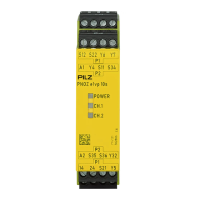
PNOZ e1vp 10 s
t
v
PNOZ e1vp 300 s
A1A1 A1
A1 A1 A1
S11
S11 S11
S11 S11 S11
S21
S21 S21
S21 S21 S21
0
0
0,15 0,5 1 2 3 5 7 10
15 25 50 100 150 200 250 300
Ein Anschlussbeispiel für PNOZ e1vp 10 s
mit einer Verzögerungszeit von 3 s finden
Sie weiter hinten in der Anleitung.
You will find a connection example for
PNOZ e1vp 10 s with a delay time of 3 s
further back in the manual.
Un exemple de raccordement pour le
PNOZ e1vp 10 s avec une temporisation
de 3 s est donné plus loin dans ce manuel.

 Loading...