PNOZ s3
Operating Manual PNOZ s3
21395-EN-10
8
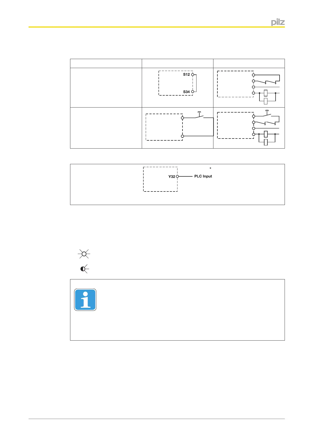
} Start circuit/feedback loop
Start circuit/feedback loop Start circuit Feedback loop
Automatic start
Manual/monitored start
} Semiconductor output
*Connect together the 0V connections on all the external power supplies
Operation
The unit is ready for operation when the Power LED is permanently lit.
LEDs indicate the status and errors during operation:
LED on
LED flashes
Information
Status indicators and error indicators may occur independently. In the case
of an error display, the "Fault" LED will light or flash (exception: "Supply
voltage too low"). An LED that is also flashing indicates the potential cause
of the error. An LED that is lit and is static indicates a normal operating sta-
tus. Several status indicators and error indicators may occur simultaneously.

 Loading...


