PNOZ s7
Operating Manual PNOZ s7
21399-EN-10
11
Preparing for operation
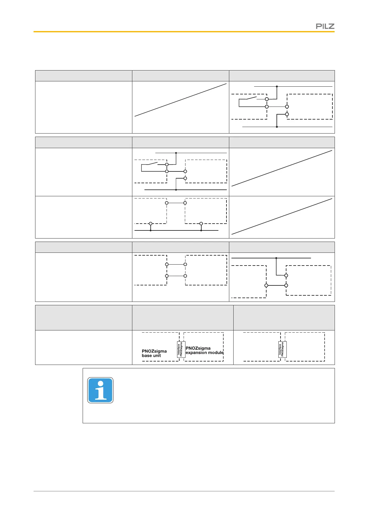
Supply voltage AC DC
A1
A2
24 V DC
0 V
PNOZsigma
expansion
module
Input circuit Single-channel Dual-channel
Base unit:
Safety relay PNOZX
A1
A2
24 V DC
0 V
PNOZsigma
expansion
module
Base unit:
Safety relay PNOZelog
Driven via semiconductor outputs
(24 VDC)
A1
A20 V
O1
L-
PNOZsigma
expansion
module
Feedback loop Base unit: Safety relay PNOZX Base unit: Safety relay PNOZelog
The inputs that evaluate the feed-
back loop will depend on the
base unit and application
52
51
feedback
loop
PNOZsigma
expansion
module
51
52
24 V DC
feedback
loop
PNOZsigma
expansion
module
Connection to PNOZsigma
base unit/PNOZmulti Mini base
unit
Base unit: Safety relay PNOZ-
sigma
Base unit: Small control system
PNOZmulti Mini
The feedback loop is connected
and evaluated via the connector
PNOZmulti Mini
base unit
PNOZsigma
expansion
module
INFORMATION
If a base unit and a contact expansion module are linked via the connector,
no additional wiring is necessary.
Do not connect A1 to the contact expansion module!

 Loading...


