Funktionsbeschreibung
Das Schaltgerät PNOZ X10 dient dem
sicherheitsgerichteten Unterbrechen eines
Sicherheitsstromkreises. Nach Anlegen der
Versorgungsspannung, Brücke zwischen
Y1-Y2 und S12 (S33)-S34 sowie geöffnetem
Eingangskreis geht Relais K3 in Wirk-
stellung.
•
Eingangskreis geschlossen (z. B. NOT-
AUS-Taster nicht betätigt)
Relais K1 und K2 gehen über die Schlies-
ser K3.1 und K3.2 in Wirkstellung und
halten sich selbst über K1.1 bzw. K2.1. Die
Statusanzeigen leuchten. Durch Öffnen
der Kontakte K1.2 und K2.2 geht K3 nach
Ablauf der Rückfallverzögerung von 180
ms in Ruhestellung. Die Sicherheitskon-
takte (13-14/23-24/33-34/43-44/53-54/63-
64) sind geschlossen, die Hilfskontakte
(71-72/81-82/91-92/01-02) sind geöffnet.
•
Eingangskreis wird geöffnet (z. B. NOT-
AUS-Taster betätigt)
K1 und K2 fallen in die Ruhestellung
zurück. Die Sicherheitskontakte (13-14/23-
24/33-34/43-44/53-54/63-64) werden
redundant geöffnet, die Hilfskontakte
(71-72/81-82/91-92/01-02) geschlossen.
Start mit Überwachung (Taster im Start-
kreis und Y1-S37 geschlossen)
Bei Betätigen des Starttasters zieht Relais
K3 an und hält sich selbst. Erst nach
Loslassen des Starttasters ist das Gerät
betriebsbereit. Relais K3 fällt ab.
Function Description
The relay PNOZ X10 provides a safety-
oriented interruption of a safety circuit.
When the operating voltage is supplied, Y1 -
Y2 and S12 (S33) - S34 are bridged and the
input circuit is closed, relay K3 energises.
• Input circuit closed (e.g. Emergency Stop
Button not activated):
Relay K1 and K2 energise via the N/O
K3.1 and K3.2 and latch via K1.1/K2.1.
The status indicators illuminate. By
opening the contacts K1.1 and K2.2, K3
de-energises following the delay-on de-
energisation of 180 ms. The safety
contacts (13-14/23-24/33-34/43-44/53-54/
63-64) are closed, the auxiliary contacts
(71-72/81-82/91-92/01-02) are opened.
• Input circuit opened (e.g. Emergency Stop
Button activated):
K1 and K2 de-energise. The safety
contacts (13-14/23-24/33-34/43-44/53-54/
63-64) are opened redundantly, the
auxiliary contacts (71-72/81-82/91-92/01-
02) are closed.
Reset with monitoring (Button in reset
circuit and Y1-S37 linked)
By pressing the reset button, relay K3
energises and retains itself. Only after
releasing the reset button is the unit ready
for operation. Relay K3 de-energises.
Description du fonctionnement
Le relais PNOZ X10 assure de façon sure,
l’ouverture d’un circuit de sécurité. A la mise
sous tension du relais (A1-A2), si Y1-Y2 et
S12 (S33)-S34 sont pontés et les canaux
d’entrée ouverts, le relais K3 colle.
•
Fermeture des canaux d’entrée
(par ex. AU non actionné) :
les relais K1 et K2 collent par l’intermédiaire
des contacts K3.1 et K3.2 et s’auto-
maintiennent par K1.1 et K2.1. Les LEDs de
visualisation sont allumées. L’ouverture des
contacts K1.2 et K2.2 fait retomber le relais
K3 qui se maintient environ 180 ms. Les
contacts de sortie de sécurité (13-14/23-24/
33-34/43-44/53-54 et 63-64) se ferment, les
contacts d’information 71-72/81-82/91-92 et
01-02 s’ouvrent.
• Ouverture des canaux d’entrée (par ex.
action sur AU):
K1 et K2 retombent. Les contacts de sortie
(13-14/23-24/33-34/43-44/53-54/63-64)
s’ouvrent de façon redondante, les contacts
d’information (71-72/81-82/91-92/01-02) se
ferment.
Surveillance du poussoir de réarmement
(pontage des bornes S1-Y37)
Une action sur le poussoir de réarmement
fait monter le relais K3 qui s'auto-maintient.
Le PNOZ X10 n'est activé qu'au relâchement
du poussoir de réarmement. Le relais K3
retombe .
Betriebsarten:
• Einkanaliger Betrieb: Eingangsbeschaltung
nach VDE 0113 und EN 60204-1, keine
Redundanz im Eingangskreis, Erdschlüsse
im Tasterkreis werden erkannt.
• Zweikanaliger Betrieb: Redundanter Ein-
gangskreis, Erdschlüsse im Tasterkreis
und Querschlüsse zwischen den Taster-
kontakten werden erkannt.
• Automatischer Start: Gerät ist aktiv,
sobald Eingangskreis geschlossen.
• Manueller Start: Gerät ist erst dann aktiv,
wenn ein Starttaster betätigt wird. Dadurch
ist ein automatischer Start des Schaltgeräts
nach Spannungsausfall und -wiederkehr
ausgeschlossen.
• Manueller Start mit Überwachung: Gerät
ist erst aktiv, wenn der Starttaster betätigt
und wieder losgelassen wurde. Dadurch
ist eine automatische Aktivierung und Über-
brückung des Starttasters ausgeschlosssen.
• Kontaktvervielfachung und -verstärkung
durch Anschluß von externen Schützen.
Operating Modes
• Single-channel operation: Input wiring
according to EN 60204-1, no redundancy in
the input circuit, earth faults are detected in
the emergency stop circuit.
• Two-channel operation: Redundancy in the
input circuit, earth faults in the emergency
stop circuit and shorts across the emer-
gency stop pushbutton will be detected.
• Automatic reset: Unit is active as soon as
the input circuit is closed.
• Manual reset: Unit is only active when a
start button has been pressed. Automatic
reset following a loss/return of supply
voltage is thereby prevented.
• Manual reset with monitoring: Unit is only
activated, when the reset button ist pressed
and then released. This prevents automatic
reset and bridging of the reset button.
• Increase in the number of available contacts
by connection of external contactors/relays.
Modes de fonctionnement
• Commande par 1 canal: conforme aux
prescriptions de la EN 60204-1, pas de
redondance dans le circuit d’entrée, la mise
à la terre du circuit d’entrée est détectée.
• Commande par 2 canaux: circuit d’entrée
redondant, la mise à la terre et les courts-
circuits entre les contacts sont détectés.
• Réarmement automatique : le relais est
activé dès la fermeture des canaux d’entrée.
• Réarmement manuel: le relais n’est activé
qu’après une impulsion sur un poussoir de
validation. Un réarmement automatique du
relais après une coupure d’alimentation est
ainsi impossible.
• Surveillance de circuit de réarmement : le
relais n'est activé qu'après le relâchement
du poussoir de validation. De ce fait un
réarmement automatique ou un pontage du
poussoir de validation est impossible.
• Augmentation du nombre de contacts ou
du pouvoir de coupure par l’utilisation de
contacteurs externes.
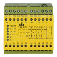
S11 13 23 33 71
14 24 34 72
K2
K1
K3
K2.2
K1.2
Y1
Y3
K3
+
~
=
F1
G1
S34
S33
K3.1 K3.2
S12S12 S22
K2
K2.1
K1
A2 (L-)A1 (L+)
K1.1
U
B
*
43
44
53
54
63
64
81
82
91 01
92
02
S11 S21 Y2
S37
K3
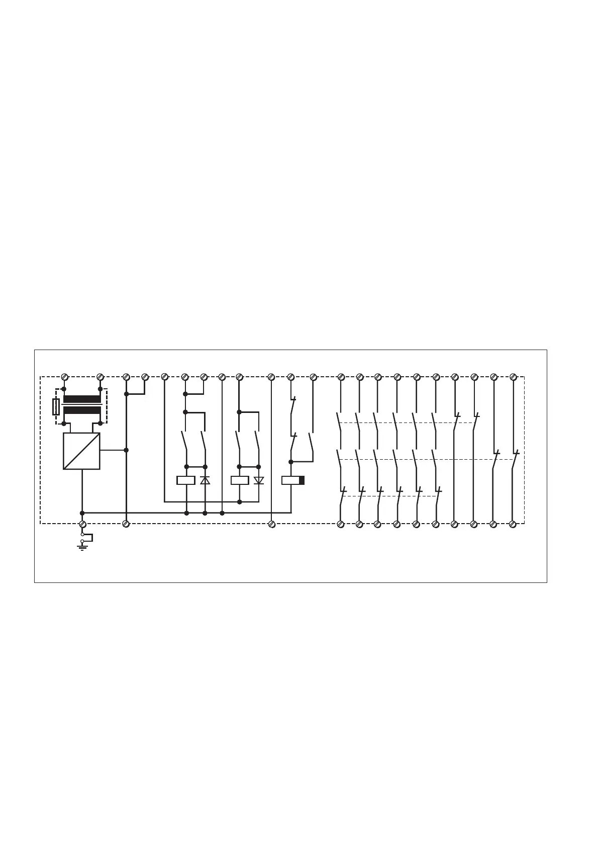
Fig. 1: Innenschaltbild/Internal Wiring Diagram/Schéma de principe
 Loading...