Installation
The safety relay must be panel mounted
(min. IP 54). There is a notch on the rear of
the unit for DIN-Rail attachment.
Operation
Please note for operation:
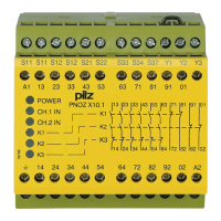
• Only the output contacts 13-14/23-24/33-
34/43-44/53-54/63-64 are safety contacts.
Output contacts 71-72/81-82/91-92/01-02
are auxiliary contacts (e.g. for a display).
• To prevent a welding together of the
contacts, a fuse (10 A quick/6 A slow
acting) must be connected before the
output contacts.
• Input Circuit
Temperature: +25 °C
Max. cable lengths:
1ch. no s/c detection:
- Cable: 1.5 mm
2
DC and AC: 2000 m
2ch. with s/c detection:
- Cable: 1.5 mm
2
DC and AC: 300 m
- Cable: 2,5 mm
2
DC and AC: 500 m
As the function for detecting shorts across
the inputs is not failsafe, it is tested by Pilz
during the final control check. However, a
test is possible after installing the unit and
it can be carried out as follows:
1. Unit ready for operation (output contacts
closed)
2. Short circuit the test (connection) terminals
S12/S22 for detecting shorts across the inputs
3. The unit‘s fuse must be triggered and the
output contacts must open. Cable lengths
in the scale of the maximum length can
delay the fuse triggering for up to 2 minutes.
4. Reset the fuse: remove the short circuit
and switch off the operating voltage for
approx. 1 minute.
• When your external device (limit switch
etc.) has a current consumption, with DC
units this must not exceed 400 mA. With
AC units no load is permitted.
• Use copper wire that will withstand
60/75 °C
• Tighten terminals to 0.6 Nm.
• Important details in the section „Technical
Data“ should be noted and adhered to.
To operate:
• Supply operating voltage to terminals
A1 (+) and A2 (-).
- DC: Connect terminal A2 (-) with the
earthed side of the operating voltage.
- AC: Connect the operating earth terminal
with the ground earth.
• Input circuit
- Single-channel: Bridge S12 - Y3 & S21 -
S22. Connect N/C contact from trigger
element (e.g. E-Stop) to S12 and S11.
- Two-channel without detection of shorts
across the contacts: Bridge S21 -S22.
Connect N/C contact from trigger element
(e.g. E-Stop) to S11 - S12/S11 - Y3
- Two-channel with detection of shorts
across the contacts: Bridge S11 -Y3.
Connect N/C contact from trigger element
(e.g. E-Stop) to S11 - S12/S21 - S22.
• Reset circuit:
Singel-channel operation and dual-channel
operation without detection of shorts across
the contacts (dual-channel switched against
+24 V DC):
- Automatic reset: Bridge S33-S34
- Manual reset: Connect button to S33-S34
- Manual reset with monitoring: Connect
button to S33-S34, bridge Y1-S37.
Dual-channel operation with detection of
shorts across the contacts:
- Automatic reset: Bridge S12-S34
- Manual reset: Connect button to S12-S34
Montage
Le relais doit être monté dans l'armoire ayant
au min. un indice de protection IP 54. Sa
face arrière permet un montage sur rail DIN.
Mise en oeuvre
Remarques préliminaires :
• Seuls les contacts 13-14, 23-24, 33-34,
43-44, 53-54, 63-64 sont des contacts
de sécurité. Les contacts 71-72, 81-82,
91-92, 01-02 sont des contacts
d’information (ex. voyant).
• Protection de contacts de sortie par
des fusibles 10A rapides ou 6 A
normaux pour éviter leur soudage.
• Circuit d’entrée
température : +25 °C
longueur maxi. câblage :
1 CH. sans détection de court-circuit
- câble : 1,5 mm
2
DC et AC: 2000 m
2 CH. avec détection de court-circuit
- câble : 1,5 mm
2
DC et AC: 300 m
- câble : 2,5 mm
2
DC et AC: 500 m
La fonction de détection de court-circuit est
testé par Pilz lors du contrôle final. Un test
sur site est possible de la façon suivante :
1. Appareil en fonction (contacts de sortie
fermés)
2. Court-circuiter les bornes de
raccordement nécessaires au test S12/S22
3. Le fusible interne du relais doit déclencher
et les contacts de sortie doivent s‘ouvrir.
Le temps de réponse du fuisible peut aller
jusqu‘à 2 min. si les longueurs de câblage
sont proches des valeurs maximales.
4. Réarmement du fusible : enlever le
court-circuit et couper l‘alimentation du
relais pendant au moins 1 min.
• Pour les relais AC, aucun autre utilisateur
ne peut être alimenté. Pour les relais en
DC, utilisateur suppl. possible jusqu’à
400 mA max.
• Utiliser uniquement des fils de cablâge en
cuivre 60/75 °C.
• Le couple de serrage sur les bornes de
racordement ne doît pas dépasser 0,6 Nm.
• Respecter les données indiquées dans le
chap. „Caractéristiques techniques“.
Mise en oeuvre :
• Amener la tension d’alimentation sur A1
et A2
- DC : borne A2 à relier au „-“
- AC : relier la borne terre
• Circuits d’entrée
- Commande par 1 canal : câblage du
contact à ouverture entre S11 et S12,
pontage de S21-S22 et S12-Y3
- Commande par 2 canaux sans
détection de courts-circuits : câblage
des contacts à ouverture entre S11-
S12/S11-Y3 , pontage de S21-S22
- Commande par 2 canaux avec
détection de courts-circuits : câblage
des contacts à ouverture entre S11-
S12/S21-S22 , pontage de S11-Y3
• Circuit de réarmement:
Commande mono-canal et en 2 canaux
sans détection de courts-circuits entre les
canaux (les 2 canaux reliés au +24 V):
- Réarmement automatique: pontage des
bornes S33-S34
- Réarmement manuel: câblage d’un
poussoir sur S33-S34
- Surveillance du circuit de réarmement:
câblage d'un poussoir sur S33-S34 et
pontage des bornes Y1-S37 .
Commande en 2 canaux avec détection
de courts-circuits:
- Réarmement automatique: pontage des
bornes S12-S34
- Réarmement manuel: câblage d’un
Montage
Das Sicherheitsschaltgerät muß in einen
Schaltschrank (min. IP 54) eingebaut werden.
Zur Befestigung auf einer Normschiene dient
ein Rastelement auf der Rückseite des Geräts.
Inbetriebnahme
Beachten Sie bei der Inbetriebnahme:
• Nur die Ausgangskontakte 13-14/23-24/
33-34/43-44/53-54/63-64 sind Sicherheits-
kontakte. Ausgangskontakte 71-72/81-82/
91-92/01-02 sind Hilfskontakte (z. B. für
Anzeige).
• Vor die Ausgangskontakte eine
Sicherung (10 A flink oder 6 A träge)
schalten, um das Verschweißen der
Kontakte zu verhindern.
• Eingangskreis
Temperatur: +25 °C
Max. Leitungslängen:
1kan. ohne Querschlußerkennung:
- Leiterquerschnitt: 1,5 mm
2
DC und AC: 2000 m
2kan. mit Querschlußerkennung:
- Leiterquerschnitt: 1,5 mm
2
DC und AC: 300 m
- Leiterquerschnitt: 2,5 mm
2
DC und AC: 500 m
Da die Funktion Querschlußerkennung nicht
einfehlersicher ist, wird sie von Pilz während
der Endkontrolle geprüft. Eine Überprüfung
nach der Installation des Geräts ist wie folgt
möglich:
1. Gerät betriebsbereit (Ausgangskontakte
geschlossen)
2. Die Testklemmen S12/S22 zur Quer-
schlußprüfung kurzschließen.
3. Die Sicherung im Gerät muß auslösen
und die Ausgangskontakte öffnen.
Leitungslängen in der Größenordnung der
Maximallänge können das Auslösen der
Sicherung um bis zu 2 Minuten verzögern.
4. Sicherung wieder zurücksetzen: den
Kurzschluß entfernen und die Versor-
gungsspannung für ca. 1 Minute abschal-
ten.
• Bei AC-Geräten kann kein zusätzlicher Ver-
braucher verwendet werden. Bei DC-Geräten
zusätzliche Verbraucher mit max. 400 mA.
• Leitungsmaterial aus Kupferdraht mit einer
Temperaturbeständigkeit von 60/75 °C
verwenden.
• Das Anzugsdrehmoment der Schrauben
auf den Anschlußklemmen darf max.
0,6 Nm betragen.
• Angaben im Kapitel „Technische Daten“
unbedingt einhalten.
Ablauf:
• Versorgungsspannung an Klemmen A1 (+)
und A2 (-) anlegen.
- DC: Klemme A2 (-) mit geerdeter Seite
der Versorgungsspannung verbinden.
- AC: Betriebserdungsklemme mit
Schutzleitersystem verbinden.
• Eingangskreis
- Einkanalig: S12-Y3 und S21-S22
brücken. Öffnerkontakt von Auslöse-
element an S12 und S11 anschließen.
- Zweikanalig ohne Querschlußer-
kennung: S21- S22 brücken; Öffner-
kontakt von Auslöseelement an S11-
S12/S11-Y3 anschließen.
- Zweikanalig mit Querschlußerkennung:
S11-Y3 brücken; Öffnerkontakt von
Auslöseelement an S11-S12/S21-S22
anschließen.
• Startkreis:
Einkanaliger Betrieb und zweikanaliger
Betrieb ohne Querschlußerkennung
(zweikanalig gegen +24 V geschaltet):
- Automatischer Start: S33-S34 brücken.
- Manueller Start: Taster zwischen S33-S34
- Manueller Start mit Überwachung:
Taster zwischen S33-S34, Y1-S37
brücken.
 Loading...