S11 S21
S12 Y2
S34
S22
Y3
S11
S12 Y1
S1
S3
Y1
S37
S11 S11
S12 Y2
S34
Y3
S21
S22
S12 Y1
S1
S3
S11 S21 S12
S12
Y1
Y2
S34S22
Y3
S12
S1
S3
Zweikanaliger Betrieb mit Querschlußer-
kennung:
- Automatischer Start: S12-S34 brücken.
- Manueller Start: Taster zwischen S12-S34
- Manueller Start mit Überwachung: Taster
zwischen S12-S34, Y1-S37 brücken.
• Rückführkreis:
Brücke an Y1-Y2 oder externe Schütze
anschließen.
Die Sicherheitskontakte sind aktiviert (ge-
schlossen) und die Hilfskontakte (71-72/81-82/
91-92/01-02) sind geöffnet. Die Statusan-
zeigen von Kanal 1 und Kanal 2 leuchten. Das
Gerät ist betriebsbereit.
Wird der Eingangskreis geöffnet, öffnen die
Sicherheitskontakte 13-14/23-24/33-34/43-44/
53-54/63-64 und die Hilfskontakte 71-72/81-
82/91-92/01-02 schließen. Die Statusanzeige
erlischt.
Wieder aktivieren
• Eingangskreis schließen.
• Bei manuellem Start zusätzlich Taster
zwischen S12 (S33) und S34 betätigen, bei
manuellem Start mit Überwachung Taster
betätigen und wieder loslassen.
Die Statusanzeigen leuchten wieder, der
Eingangskreis ist aktiviert.
- Manual reset with monitoring: Connect
button to S12-S34, bridge Y1-S37.
• Feedback control loop:
Bridge Y1 - Y2 or connect external N/C
contacts in series from other devices .
The safety contacts are activated (closed)
and the auxiliary contacts (71-72/81-82/91-
92/01-02) are open. The status indicators
from channel 1 and channel 2 are
illuminated. The unit is ready for operation.
If the input circuit is opened, the safety
contacts 13-14/23-24/33-34/43-44/53-54/63-
64 open and the auxiliary contacts 71-72/81-
82/91-92/01-02 close. The status indicator
goes out.
Reactivation
• Close the input circuit.
• For manual reset, momentary closure of the
button between S12 (S33) and S34 must be
pressed; for manual reset with monitoring,
press the button and release again.
The status indicators illuminate once more,
the input circuit is activated.
poussoir sur S12-S34
- Surveillance du circuit de réarmement:
câblage d'un poussoir sur S12-S34 et
pontage des bornes Y1-S37.
• Boucle de retour:
Pontage de Y1-Y2 ou branchement des
contacts externes
Les contacts de sortie se ferment et les
contacts d’info (71-72/81-82/91-92/01-02)
s’ouvrent. Les LEDs de visualisation des
canaux 1 et 2 sont allumées. L’appareil est
prêt à fonctionner.
Si le circuit d’entrée est ouvert, les contacts de
sortie 13-14/23-24/33-34/43-44/53-54/63-64
s’ouvrent et les contacts d’inform 71-72/81-82/
91-92/01-02 se ferment. Les LEDs s’éteignent.
Remise en route :
• fermer le(s) circuit(s) d’entrée
• en cas de réarmement manuel, appuyer
sur le poussoir de validation entre S12
(S33)-S34. En cas de surveillance du
circuit de réarmement, appuyer puis
relacher le poussoir de validation.
Les LEDs sont à nouveau allumées. Les
contacts de sortie sont fermées.
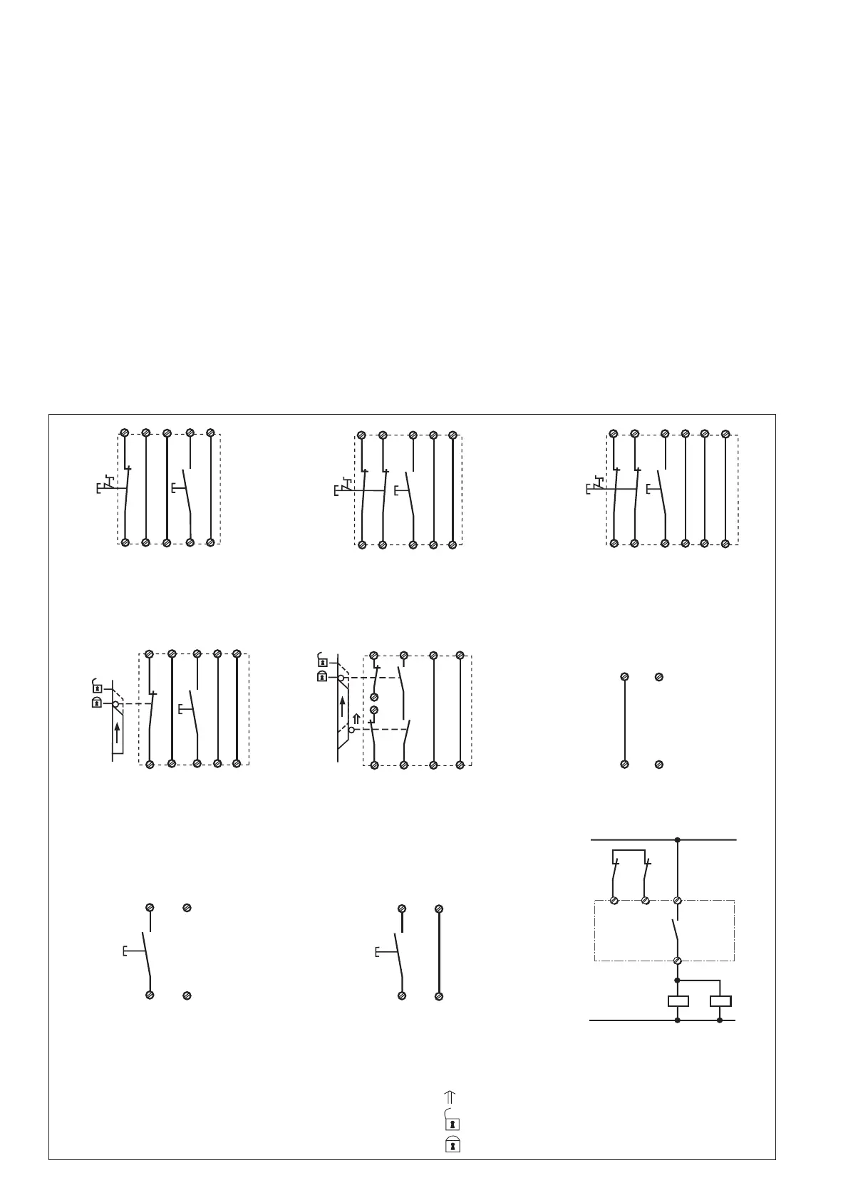
Fig. 2: Eingangskreis einkanalig/Single-
channel input circuit/Commande par 1 canal
Fig. 3: Eingangskreis zweikanalig ohne
Querschlußerkennung/Two-channel input
circuit; no short-circuit recognition/Commande
par 2 canaux sans détection des c. c.
Y2
S34
Y3
S12
S12 Y1
S11
S22
S12
S21
S1
S3
Fig. 5: Schutztürsteuerung einkanalig/Single
channel safety gate control/Surveillance de
protecteur, commande par 1 canal
Fig. 8: Manueller Start/Manual reset/
Rearmement manuel
Fig. 4: Eingangskreis zweikanalig, überwach-
ter Start mit Querschlußerkennung/Two-
channel input circuit, monitored reset with
short-circuit recognition /Commande par 2
canaux, surveillance du poussoir de
validation avec détection des c. c.
S1/S2: NOT-AUS- bzw. Schutztürschalter/Emergency Stop Button,
Safety Gate Limit Switch/Poussoir AU, détecteurs de
position
S3: Starttaster/Reset button/Poussoir de réarmement
S37
Y1
S34
S12 (S33)
S3
Fig. 9: Manueller Start mit Überwachung/
Manual reset with monitoring/Surveillance de
circuit de réarmement
Fig. 6: Schutztürsteuerung zweikanalig,
automatischer Start/Two channel safety gate
control,automatic reset/Surveillance de
protecteur, commande par 2 canaux,
validation automatique
Y3
S34
S33
S11
S21
S12
S22
S1
S2
S11
Y2
Y1
14
K4 K5
13
Y1 Y2
K4
K5
1L1
1L2
Fig. 10: Anschlußbeispiel für externe Schütze/
Connection example for external Contactors,
relays/Branchement contacteurs externes
Fig. 7: Automatischer Start/Automatic reset/
Rearmement automatique
S34
S12 (S33)
S37
Y1
Tür nicht geschlossen/Gate open/porte ouverte
betätigtes Element/Switch activated/élément actionné
Tür geschlossen/Gate closed/porte fermée
S37
Y1
S34
S12 (S33)
S3
 Loading...