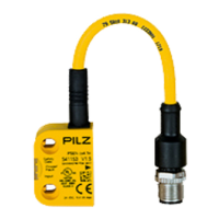
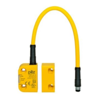
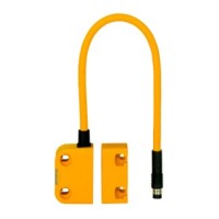
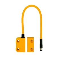
PSEN cs4.1 M12/8-1.5m
Operating Manual PSEN cs4.1 M12/8-1.5m
1003810-EN-07
| 10
Function description
Basic function
The safety outputs may have a high or low signal, depending on the position of the actuator
and the signal status of the inputs.
In a safe condition the safety outputs are in the OFF state.
Electrical states of the inputs and outputs (when safety switch is ready for operation:
Power/Fault LED is green):
Actuator
within the
response
range
Safety input
S11
Safety input
S21
Safety out-
put 12
Safety out-
put 22
Signal out-
put Y32
(without use
of the SDD)
Yes High High High High High
Yes Low Low Low Low High
No x x Low Low Low
Yes High Low High Low High
Yes Low High Low High High
x: High or low signal
Plausibility monitoring for safety inputs S11 and S21
} If one safety input switches from high to low, while the other safety input remains high, an
unequal status is displayed: Input LED flashes yellow
} If this safety input switches back from low to high, while the other safety input remains
high, a plausibility error is displayed and a partial operation lock is triggered: Input LED
flashes yellow
A switch to a high signal will only lead to normal safety switch operation if both inputs had a
low signal. From this moment on, the switch to high may occur (partial operation lock see
Error display [ 31]).
} Diagnostic input Y1
If a fieldbus module of the SDD is used, the diagnostic input Y1 is automatically activated
and data is read.
If no fieldbus module of the SDD is used, the diagnostic input Y1 is not used.
} Signal output/diagnostic output Y32 in SDD mode
If a fieldbus module of the SDD is used, the signal output/diagnostic output Y32 is activ-
ated for writing data.