PZA
Operating Manual PZA
18219-EN-07
7
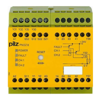
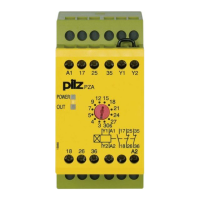
Unit features
} Positive-guided relay outputs:
– 1 safety contact (N/O), delay-on energisation
– 2 auxiliary contacts (N/C), delay-on energisation
} LED display for:
– Supply voltage
– Switch state safety output
} 12 time values, set via rotary switch
} Feedback loop for monitoring external contactors
} See order reference for unit types
Safety features
The relay meets the following safety requirements:
} The circuit is internally redundant with built-in self-monitoring.
} The safety device remains effective in the case of a component failure.
} The correct opening and closing of the safety device relays is tested automatically in
each on-off cycle.
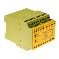
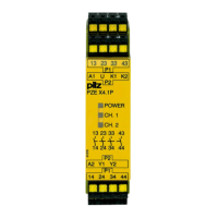
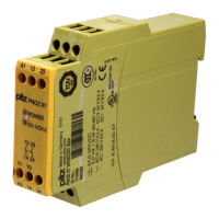
Block diagram/terminal configuration
Types: AC
} U
B
: 24 V AC; Order no. 774020, 774031
} U
B
: 110 - 120 VAC; Order no. 774023, 774035
} U
B
: 230 V AC; Order no. 774026, 774038, 774040
*Insulation between the non-marked area and the relay contacts: Basic insulation (over-
voltage category III), Protective separation (overvoltage category II)
 Loading...