*Insulationbetweenthenonmarkedareaandtherelaycontacts:Basicinsulation(over
voltagecategoryIII),Protectiveseparation(overvoltagecategoryII)
Functiondescription
Thecontactexpansionmoduleisanaddondevicewithoutdelayondeenergisation,andit
isusedtoexpandasafetycircuit.Thecontactexpansionmoduleisdrivenbyabaseunit
(e.g.emergencystoprelay).
}
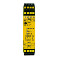
Functionalprocedureafterclosingthesafetycontactsofthebaseunit:
– Thesupplyvoltageispresentattheinput(A1)ofthecontactexpansionmodule.
– Closethesafetycontacts1314,2324,3334and4344.
– TheLEDs"CH.1"and"CH.2"arelit.
}
Functionalprocedureafteropeningthesafetycontactsofthebaseunit:
– Thereisnotsupplyvoltageatinput(A1)ofthecontactexpansionmodule.
– Openthesafetycontacts1314,2324,3334and4344.
– TheLEDs"CH.1"and"CH.2"goout.
Installation
}
TheunitshouldbeinstalledinacontrolcabinetwithaprotectiontypeofatleastIP54.
}
UsethenotchontherearoftheunittoattachittoaDINrail.
}
EnsuretheunitismountedsecurelyonaverticalDINrail(35mm)byusingafixingele
ment(e.g.retainingbracketoranendangle).
}
Ifmorethan2unitsareinstallednexttoeachotherinthecontrolcabinet,leaveadis
tanceofatleast6mmbetweentheunits.

 Loading...