11
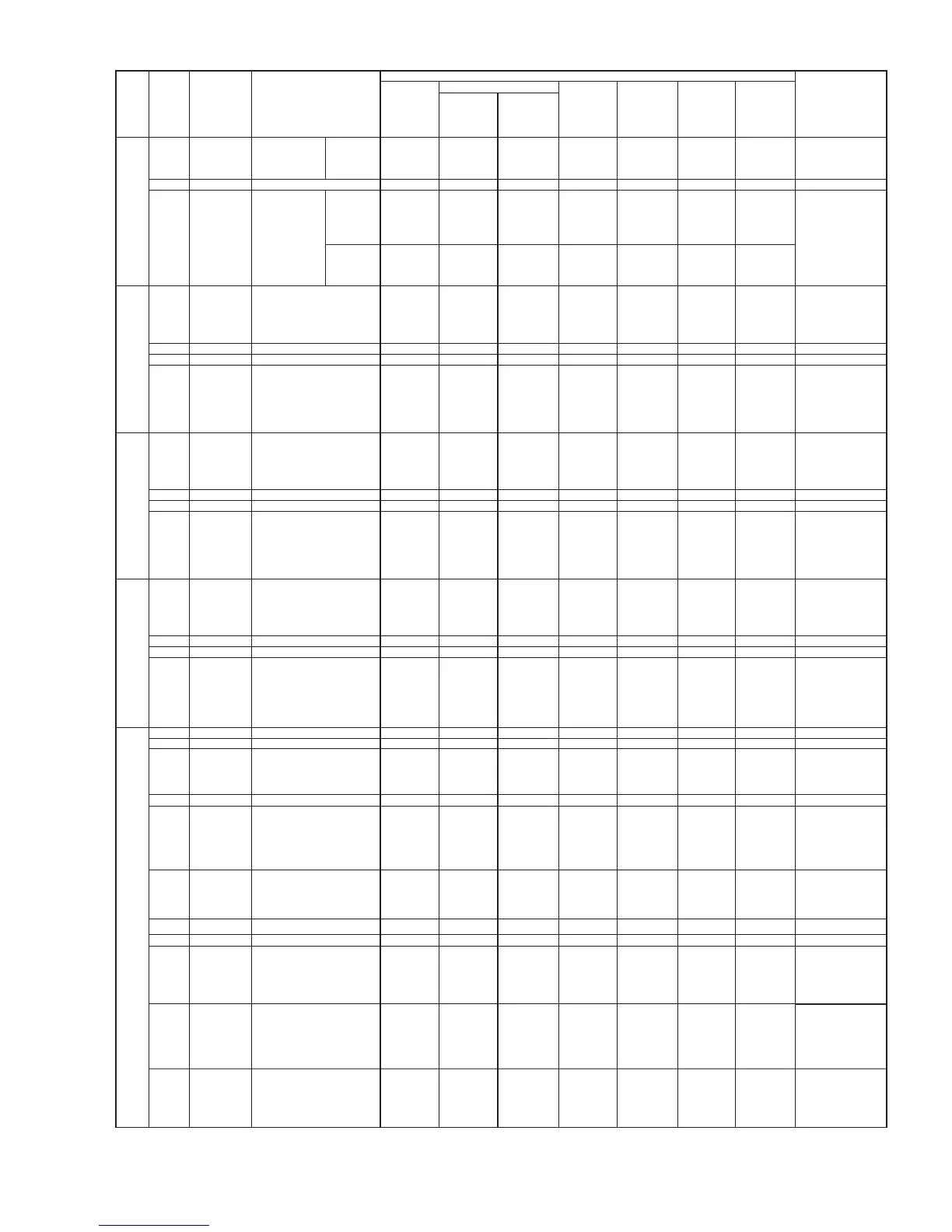
232C_SHUT
ON/OFF
MAIN→RS232C
12 REM
Insertion detection
for wired
remotecontrol
input
RS232C→MAIN
(NC for Model R)
TM 1 SCL5
Clock line of the I2C bus
MAIN→SENB
2GND GND --
3 VDD+3.3V
3.3V power supply for analog signals
MAIN→SENB
4 SDA5
Data line of the I2C bus
MAIN←→SENB
TR 1 SCL5
Clock line of the I2C bus
Clock line of the I2C bus
SENB→SEND
2GND GND --
3 VDD+3.3V
3.3V power supply for analog signals
SENB→SEND
4 SDA5
Data line of the I2C bus
SENB←→SEND
TS 1 SCL5 SEND→SENC
2GND GND --
3 VDD+3.3V
3.3V power supply for analog signals
SEND→SENC
4 SDA5
Data line of the I2C bus
SEND←→SENC
AD 1 GND
GND
GND --
MAIN→FAN
0
0
-
0
0
0
0
0
0
0
0
0
0
0
0
0
0
0
0
0
0
-
0
0
0
0
0
0
0
0
0
0
0
0
0
0
0
0
3.3
-
0
0
0
0
0
0
0
0
0
0
0
0
0
0
0
0
3.3
-
0
0
0
0
0
0
0
0
0
0
0
0
0
0
0
0
3.3
-
0
3.3
0
0
0
3.3
3.3
-
0
3.3
0
0
0
3.3
-
-
-
-
-
-
-
-
-
-
-
-
-
-
-
-
-
-
AC power
OFF(Power
cordpulled
out ofthe wall
outlet)
AC power ON
(Power
cordconnected
tothe wall outlet)
Basic operation (Numerical unit: Vdc; except for the case when units are individually indicated)
No signal With signal
Signal direction
Main power ON (POWER button ON)
Power
management
Standby
Main power
OFF
name
Pin NO
Pin name Function
5Vdc during
normal PDP
operation; 0V
when the PDP
is out of order.
5Vdc during
normal PDP
operation; 0V
when the PDP
is out of order.
During data
exchange:Clock
signal(3.3Vac),
Data not
exchanged:
3.3Vdc
During data
exchange:Clock
signal(3.3Vac),
Data not
exchanged:
3.3Vdc
During data
exchange:Clock
signal(3.3Vac),
Data not
exchanged:
3.3Vdc
Clock signal
used during
transmission
(3.3Vac)3.3Vdc
when no data
are transmitted.
3.3V when
a wired
remotecontrol is
connected/When
not connected.
3.3V when
a wired
remotecontrol is
connected/When
not connected.
3.3V when
a wired
remotecontrol is
connected/When
not connected.
3.3V when
a wired
remotecontrol is
connected/When
not connected.
Clock signal
used during
transmission
(3.3Vac)3.3Vdc
when no data
are transmitted.
Clock signal
used during
transmission
(3.3Vac)3.3Vdc
when no data
are transmitted.
During data
exchange:Clock
signal(3.3Vac),
Data not
exchanged:
3.3Vdc
During data
exchange:Clock
signal(3.3Vac),
Data not
exchanged:
3.3Vdc
During data
exchange:Clock
signal(3.3Vac),
Data not
exchanged:
3.3Vdc
Clock signal
used during
transmission
(3.3Vac)3.3Vdc
when no data
are transmitted.
Clock signal
used during
transmission
(3.3Vac)3.3Vdc
when no data
are transmitted.
Clock signal
used during
transmission
(3.3Vac)3.3Vdc
when no data
are transmitted.
2GND
3 ALARM Module alarm signal PDP
→
MAIN
4 GND GND
0
0
00
0
0
0
0
0
0
0
0
GND
0
0
0
0
00
0
0
0
0
0
0
000
-
-
-
-
-
-
0
0-
-
-
-
-
-
-
-
-
-
-
-
-
-
-
-
-
-
-
-
0
00
0
0
0
0
0
-
-
-
5 PS+
MSEL
GND
PSS input PS+
PDP
→
MAIN
6 PS-
PSS input PS-
PDP
→
MAIN
PSS LVDS
serial differential
PS+ input
0Vac; Bias
1.4Vdc
PSS LVDS
serial differential
PS+ input
0Vac; Bias
1.1Vdc
PSS LVDS
serial differential
PS+ input
0.3Vac; Bias
1.25Vdc
PSS LVDS
serial differential
PS+ input
0.3Vac; Bias
1.25Vdc
7
8
42V5 compatible interface OFF
9 RH+
OSD system output H+
MAIN
→
PDP
10 RH-
OSD system output H-
MAIN
→
PDP
11 RG+
OSD system output G+
MAIN
→
PDP
OSD LVDS
serial
differential
G+ output
0.3Vac;Bias
1.25Vdc
OSD LVD
Sserial
differential
H- output
0Vac ;Bias
1.4Vdc
OSD LVD
Sserial
differential
H+ output
0Vac ;Bias
1.1Vdc
OSD LVD
Sserial
differential
H- output
0Vac ;Bias
1.4Vdc
OSD LVD
Sserial
differential
H+ output
0Vac ;Bias
1.1Vdc
OSD LVDS
serial
differential
G+ output
0.3Vac;Bias
1.25Vdc
 Loading...