116
13-1
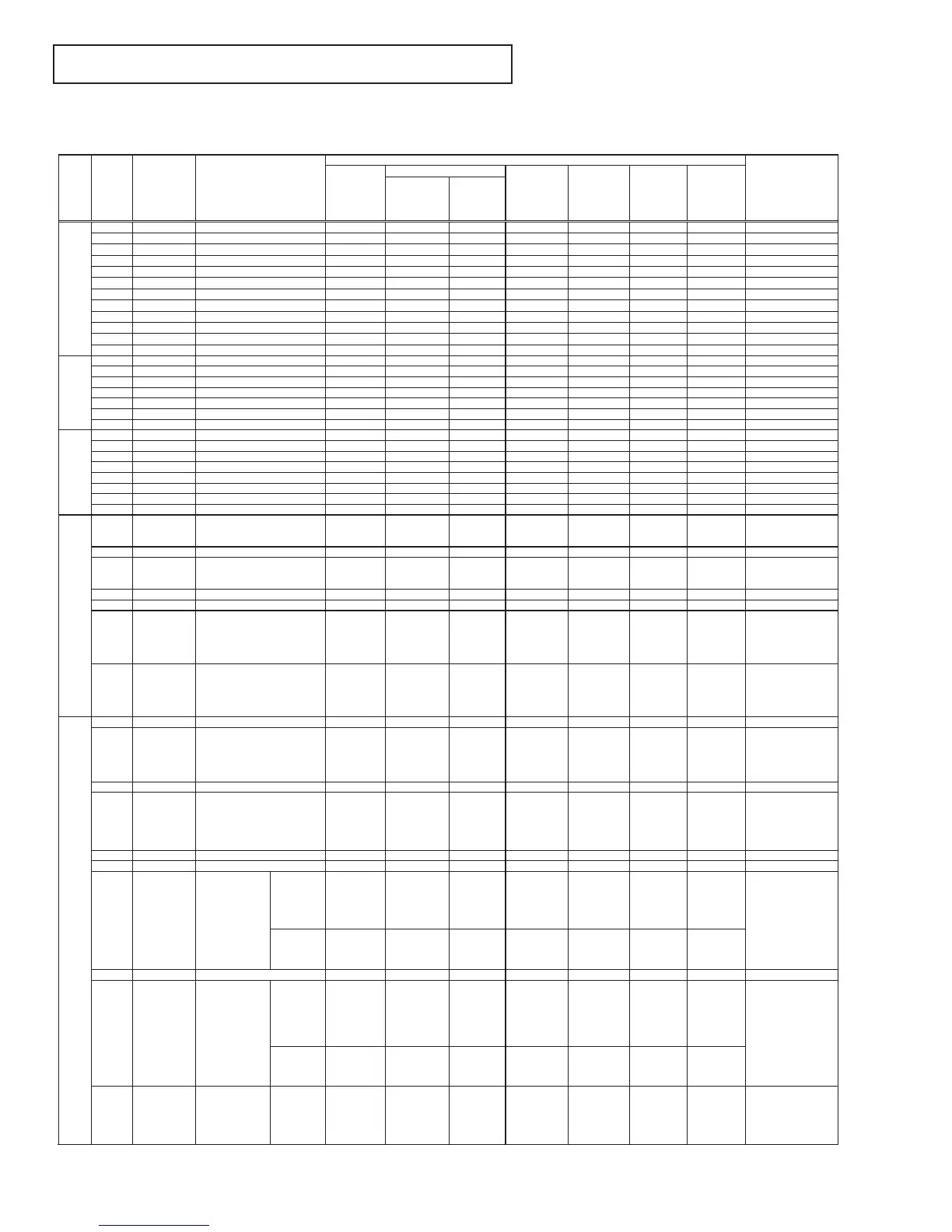
PDP-424MV/PDP-424MV-FI/PDP-42MVE1 Series
PDP-424MV/PDP-424MV-FI/PDP-42MVE1 Series
(Caution)The operating voltages specified below are used in common irrespective of the presence of signals.In this case,however,part of the operating voltages (red characters)may
change according to the signal conditions when the main power supply is turned on (POWER button ON).
Status of LED lighting:♦ for lighting in green,,♦♦ for unlighting,,and ♦♦♦ for lighting in red..
Ver.1
PN 1 D+3.3
3.3V power supply for digital circuits
0
0
0
0
0
0
0
0
0
0
0
0
6.8
0
0
0
4.8
0
-
0
0
0
0
0
0
-
-
0
0
0
0
3.5
0
0
0
0
0
0
0
0
0
-
0
0
0
0
0
0
0
0
0
0
0
0
0
0
6.8
0
0
0
4.8
0
-
0
0
0
0
0
0
-
-
0
0
0
0
3.5
0
0
0
0
0
0
0
0
0
-
0
0
3.3
3.3
3.3
0
0
0
2.5
2.5
2.5
0
0
0
6.8
0
4.9
0
4.8
6.8
-
12
0
6
6
0
0
-
-
0
0
3.5→0
5
0
3.3
0
-
3.3
3.3
3.3
0
0
0
2.5
2.5
2.5
0
0
0
6.8
0
4.9
0
4.8
6.8
-
12
0
6
6
0
0
-
-
0
0
3.5→0
5
0
3.3
0
-
0
0
0
0
0
0
0
0
0
0
0
0
6.8
0
0
0
4.8
6.8
-
0
0
0
0
0
0
-
-
0
0
0
0
3.5→0
0
1
5
0
3.3
0
-
0
0
0
0
0
0
0
0
0
0
0
0
6.8
0
0
0
4.8
6.8
-
0
0
0
0
0
0
-
-
0
0
0
0
3.5→0
0
1
5
0
3.3
0
-
0
0
-
-
-
-
-
-
-
-
-
-
-
-
-
-
-
-
4.8→-
-
-
-
-
-
-
-
-
-
-
-
-
-
-
3.5→-
-
-
-
-
-
-
-
-
-
-
-
-
POWER → MAIN
2 D+3.3
3.3V power supply for digital circuits
POWER → MAIN
3 D+3.3
3.3V power supply for digital circuits
POWER → MAIN
4D.GND GND -
5D.GND GND -
6D.GND GND -
7 D+2.5
2.5V power supply for digital circuits
POWER → MAIN
8 D+2.5
2.5V power supply for digital circuits
POWER → MAIN
9 D+2.5
2.5V power supply for digital circuits
POWER → MAIN
10 D.GND GND -
11 D.GND GND -
12 D.GND GND -
PM 1 M+7
7V power supply for microcomputer
POWER → MAIN
2D.GND GND -
3 POWER
Power control
MAIN → POWER
4D.GND GND -
5 POMUTE
Mute signal for AC power OFF
POWER → MAIN
6 SW7
Power start control
POWER → MAIN
7
NC
Non-connection terminal
-
PV 1 A+12
12V power supply for analog circuits
POWER → MAIN
2A.GND GND -
3 A+6
6V power supply for analog circuits
POWER → MAIN
4 A+6
6V power supply for analog circuits
POWER → MAIN
5A.GND GND -
6A.GND
NC
NC
GND -
7
Non-connection terminal
-
8
Non-connection terminal
-
AU 1 AU_L
Audio signal L
CH
MAIN → AUDIO
2GND GND -
3 AU_R
Audio signal R
MAIN → AUDIO
4GND GND -
5 MUTE
Mute signal of audio output
MAIN → AUDIO
6 SCL7
Clock line of the I2C bus
MAIN → AUDIO
7 SDA7
Data line of the I2C bus
MAIN → AUDIO
RS 1 M+5V
5V power supply for microcomputer
MAIN → RS232C
2 TXD
RS232 driver output
MAIN → RS232C
3GND GND -
4 RXD
RS232 receiver input
RS232C → MAIN
5
6
M+3.3V
3.3V power supply for microcompute
MAIN → RS232C
GND G N D -
7
REMIN2/RXD
1
Data signal of
wired remote
control
RS232C → MAIN
8 RESET SW NC -
9 PLE_CTL
PLE control
MAIN → RS232C
10 TXD1
RS232 driver
output
MAIN → RS232C
AC power
OFF(Power
cordpulled
out ofthe wall
outlet)
AC power ON
(Power
cordconnected
tothe wall outlet)
Basic operation (Numerical unit: Vdc; except for the case when units are individually indicated)
No signal With signal
Signal direction
Main power ON (POWER button ON)
Power
management
Standby
Main power
OFF
name
Pin NO
Pin name Function
Clock signalused
during data
transmission
(5Vac)5Vdc
when no data
are transmitted.
Clock signal
(5Vac) when
data are
received; 5Vdc
when no data
are received.
Clock signal
(5Vac) when
data are
received; 5Vdc
when no data
are received.
Clock signal
(5Vac) when
data are
received; 5Vdc
when no data
are received.
Clock signal
(5Vac) when
data are
received; 5Vdc
when no data
are received.
Selected input
signals are
output.
Selected input
signals are
output.
Selected input
signals are
output.
Selected input
signals are
output.
3.3V duning
data
transmission for
Video WOLL 0V
when no data
are
transmitted
Clock signal
(3.3Vac) when
data are
received;3.3Vdc
when no data
are received.
Clock signal
(3.3Vac) when
data are
received;3.3Vdc
when no data
are received.
Clock signal
(3.3Vac) when
data are
received;3.3Vdc
when no data
are received.
Clock signal
(3.3Vac) when
data are
received;3.3Vdc
when no data
are received.
Clock signal
(3.3Vac) when
data are
received;3.3Vdc
when no data
are received.
Clock signal
(3.3Vac) when
data are
received;3.3Vdc
when no data
are received.
Clock signal
(3.3Vac) when
data are
received;3.3Vdc
when no data
are received.
Clock signal
(3.3Vac) when
data are
received;3.3Vdc
when no data
are received.
Clock signal
(3.3Vac) when
data are
received;3.3Vdc
when no data
are received.
Clock signal
(3.3Vac) when
data are
received;3.3Vdc
when no data
are received.
Clock signal
(3.3Vac) when
data are
received;3.3Vdc
when no data
are received.
Clock signal
(3.3Vac) when
data are
received;3.3Vdc
when no data
are received.
3.3V duning
data
transmission for
Video WOLL 0V
when no data
are
transmitted
3.3V duning
data
transmission for
Video WOLL 0V
when no data
are
transmitted
Clock signalused
during data
transmission
(5Vac)5Vdc
when no data
are transmitted.
Clock signalused
during data
transmission
(5Vac)5Vdc
when no data
are transmitted.
CONNECTOR PIN EXPLANATION
 Loading...