119
13-5
5 GND
GND
GND
GND
GND GND
GND GND
GND GND
GND GND
-
6
-
-
-
-
-
-
-
-
-
-
-
-
-
-
LD 1 REMIN1
Infrared remote control data
LED
→
PWR
2 LEDCTL1
Standby red LED control
PWR
→
LED
3 LEDCTL2
POWER ON green LED control
PWR
→
LED
4
5M+5V
5V power supply for microcomputer
PWR
→
LED
PW 1 SW7
Power start control
PW
→
MAIN
2
3
POIN
Power start detection
PW
→
MAIN
4M+5V
5V power supply for microcomputer
MAIN
→
PW
5M+7V
7V power supply for microcomputer
MAIN
→
PW
6REMIN1
Infrared remote control data
PW
→
MAIN
7 LEDCTL1
Standby red LED control
MAIN
→
PW
8 LEDCTL2
POWER ON green LED control
MAIN
→
PW
SW 1 CTL1
Key input detection
SW
→
MAIN
2CTL2
Key input detection
SW
→
MAIN
3 -
-
-
PA 1 S+12
+12V power supply for audio circuits
+12V power supply for audio circuits
+12V power supply for audio circuits
POWER
→
AUDIO
2 S+12 POWER
→
AUDIO
3 S+12 POWER
→
AUDIO
4 -
-
-
-
-
-
-
-
-
-
-
-
-
-
-
-
-
-
-
-
-
-
-
-
-
-
0
0
0
0
0
0
0
0
0
0
0
0
0
0
0
0
0
0
0
0
0
0
0
0
0
0
0
0
0
0
0
0
0
0
0
0
0
0
0
-
0
0
0
0
0
0
AC power
OFF(Power
cordpulled
out ofthe wall
outlet)
AC power ON
(Power
cordconnected
tothe wall outlet)
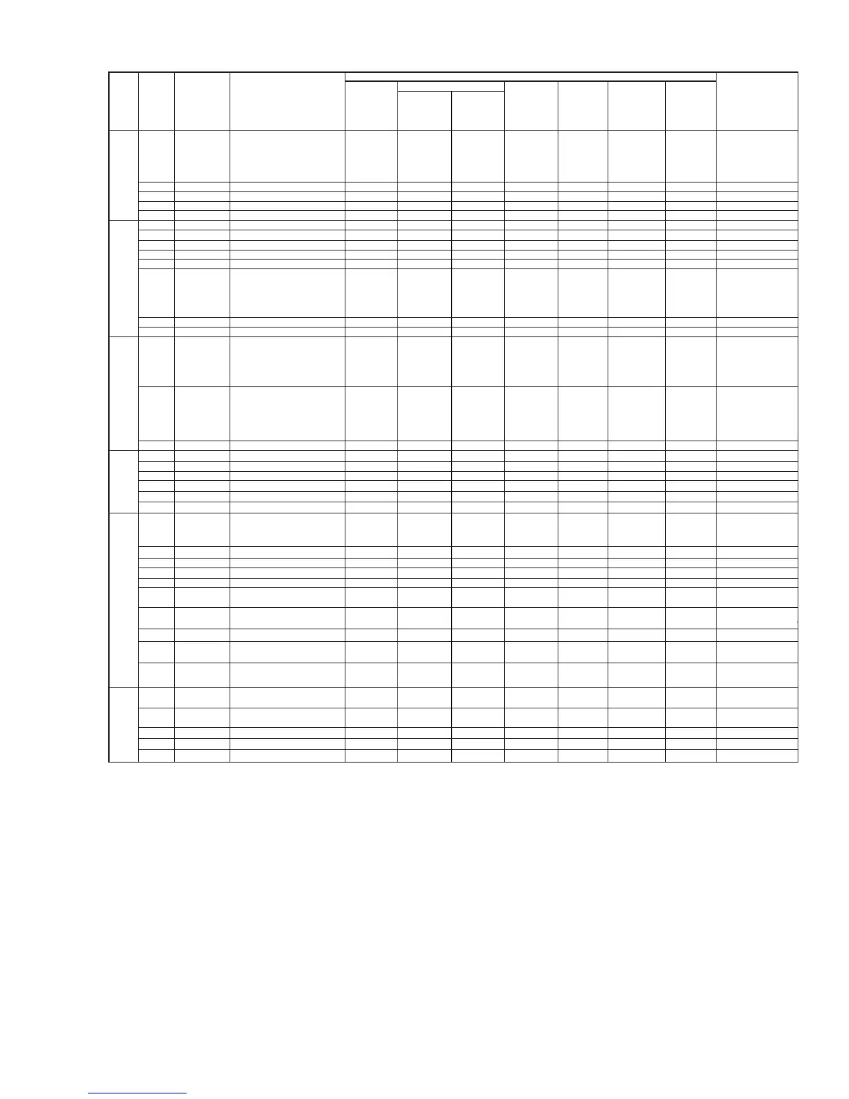
Basic operation (Numerical unit: Vdc; except for the case when units are individually indicated)
No signal With signal
Signal direction
Main power ON (POWER button ON)
Power
management
Standby
Main power
OFF
name
Pin NO
Pin name Function
Clock signal
(5Vac) when
data are
received; 5Vdc
when no data
are received.
0.7~2.8Vdc
when keyinputs
are entered;
3.3Vdc when no
key inputs are
entered.
0.7~2.8Vdc
when key inputs
are entered;
3.3Vdc when no
key inputsare
entered.
0.7~2.8Vdc
when key inputs
are entered;
3.3Vdc when no
key inputsare
entered.
0.7~2.8Vdc
when key inputs
are entered;
3.3Vdc when no
key inputsare
entered.
0.7~2.8Vdc
when key inputs
are entered;
3.3Vdc when no
key inputsare
entered.
0.7~2.8Vdc
when keyinputs
are entered;
3.3Vdc when no
key inputs are
entered.
0.7~2.8Vdc
when keyinputs
are entered;
3.3Vdc when no
key inputs are
entered.
0.7~2.8Vdc
when keyinputs
are entered;
3.3Vdc when no
key inputs are
entered.
Clock signal
(5Vac) when
data are
received; 5Vdc
when no data
are received.
Clock signal
(5Vac) when
data are
received; 5Vdc
when no data
are received.
Clock signal
(5Vac) when
data are
received; 5Vdc
when no data
are received.
Clock signal
(5Vac) when
data are
received; 5Vdc
when no data
are received.
Clock signal
(5Vac) when
data are
received; 5Vdc
when no data
are received.
Clock signal
(5Vac) when
data are
received; 5Vdc
when no data
are received.
Clock signal
(5Vac) when
data are
received; 5Vdc
when no data
are received.
0
12
12
12
0
0
12
12
12
0
0
3.3
0
3.3
0
3.3
0
0
6.8
3.3
0
5
6.8
-
-
0
3.3
0
0
6.8
3.3
0
5
6.8
0
0
0
0
0
0
0
0
0
0
0
0
0
0
0
0
0
00
0
0
0
0
0
0
0
0
-
0
00
000
000
00
00
00
0
0
0
-
00
0
0
000
0
-
0
0
0
0
0
0
0
0
0
0
0
0
0
00 0
0
PD 1 ALARM PDP alarm signal PDP
→
POWER
2D.GND GND
3D.GND GND
4D.GND GND
5D.GND GND
6 D+60 Vd power supply
for PDP
PDWER
→
PDP
7 D+60 PDWER
→
PDP
5Vdc when the
PDP is normal;
0V when it is
abnormal.
5Vdc when the
PDP is normal;
0V when it is
abnormal.
60Vdc(changeable
according to the PDP)
60Vdc(changeable
according to the PDP)
60Vdc(changeable
according to the PDP)
60Vdc(changeable
according to the PDP)
8
NC
digital circuits
9 D+170
Vs power supply
for PDP high-voltage
circuits
PDWER
→
PDP
10 D+170
Vs power supply
for PDP high-voltage
circuits
PDWER
→
PDP
170Vdc(changeable
according to the PDP)
170Vdc(changeable
according to the PDP)
170Vdc(changeable
according to the PDP)
170Vdc(changeable
according to the PDP)
PH 1 D+5 5V power supply for
digital circuits
5V power supply for
digital circuits
PDWER
→
PDP
2 D+5 PDWER
→
PDP
3D.GND GND
4D.GND GND
5.15
5.15
5.15
5.15
 Loading...