64
9-2
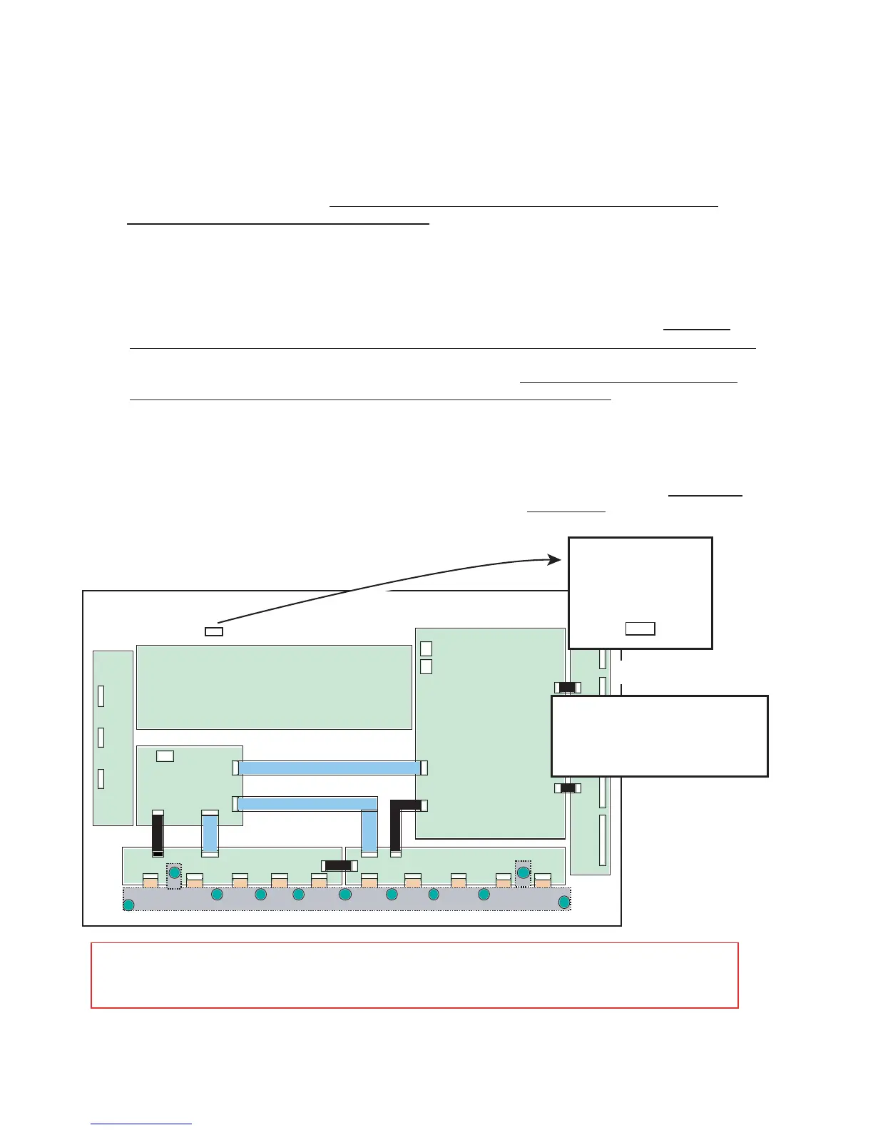
Common relay PKG
Digital PKG
Signal relay PKG(right)
Signal relay PKG(left)
Scanning relay PKG-U
Scanning relay
PKG-D
Common divergencePKG
High voltage PKG
SERIAL NO.
********
Vd= **V
Vs=***V
CODE -01
Vs/Vd/100/185/220 V
555/84.2/782/10204 K
347 W/0 /2 P
OR
2-1. Adjustment of the Vs voltage
Enter a color bar input by means of either video signal of VIDEO input, or DVD/HD input, or RGB input,
and turn on the power switch of the main unit.
Turn the volume control (RV6) in the power unit and make adjustments until the voltages of CH2 and CH1
(D, GND) of the power unit attain the voltage values specified for the PDP (Vs value of the voltage
regulation indicator label on below the figure) ±1V.
2-2. Adjustment of the Vd voltage
Enter a color bar input by means of either video signal of VIDEO input, or DVD/HD input, or RGB input,
and turn on the power switch of the main unit.
Confirm that the voltages of CH4 and CH1 (D, GND) of the power unit are maintained at the voltage
values specified for the PDP (Vd value of the voltage regulation indicator label on below the figure) ±1V.
Otherwise, turn the volume control (RV5) until the voltage attains the voltage values specified for the
PDP (Vd value of the voltage regulation indicator label on below the figure) ±1V.
2-3. Adjustment of the +5V voltage
Display a color bar by means of either video signal of VIDEO input, or DVD/HD input, or RGB input.
Confirm that the voltages of CH3 and CH1 (D, GND) of the power unit are maintained at "5.15 ± 0.1V".
Otherwise, turn the volume control (RV2) until the voltage attains "5.15 ± 0.1V".
(Caution) Rear-side view when the back cover is removed The label is concealed between the MAIN
PWB and PDP. Check it by peeping through the space from above. The label position can be
changed, without notice.
2. Adjustment of the power unit (Using a screwdriver for general-purpose
adjustments)
(1)
(2)
(1)
(2)
(1)
(2)
 Loading...