EasyManua.ls Logo

Pioneer XR-A330 Service Manual

Pioneer XR-A330
82 pages
To Next Page IconTo Next Page
Page #1 background imageLoading...
Page #1 background image
ORDER NO.
PIONEER ELECTRONIC CORPORATION 4-1, Meguro 1-Chome, Meguro-ku, Tokyo 153-8654, Japan
PIONEER ELECTRONICS SERVICE, INC. P.O. Box 1760, Long Beach, CA 90801-1760, U.S.A.
PIONEER ELECTRONIC (EUROPE) N.V. Haven 1087, Keetberglaan 1, 9120 Melsele, Belgium
PIONEER ELECTRONICS ASIACENTRE PTE. LTD. 253 Alexandra Road, #04-01, Singapore 159936
PIONEER ELECTRONIC CORPORATION 1998
RRV2064
CONTENTS
T – ZZK DEC. 1998 Printed in Japan
1. SAFETY INFORMATION ...................................... 2
2. EXPLODED VIEWS AND PARTS LIST ................ 4
3. SCHEMATIC DIAGRAM ..................................... 18
4. PCB CONNECTION DIAGRAM .......................... 34
5. PCB PARTS LIST ............................................... 46
6. ADJUSTMENT .................................................... 53
7. GENERAL INFORMATION ............................... 62
7.1 PARTS ......................................................... 62
7.1.1 IC ......................................................... 62
7.1.2 DISPLAY.............................................. 69
7.2 DISASSEMBLY ........................................... 73
7.3 BLOCK DIAGRAM....................................... 76
8. PANEL FACILITIES AND SPECIFICATIONS .... 78
STEREO CD CASSETTE DECK RECEIVER
XR-A660
XR-A330
THIS MANUAL IS APPLICABLE TO THE FOLLOWING MODEL(S) AND TYPE(S).
XR-A660
Type
Model
Power Requirement Remarks
XR-A660 XR-A330
KUCXJ AC120V
YPWXJ AC240V

Other manuals for Pioneer XR-A330

Question and Answer IconNeed help?

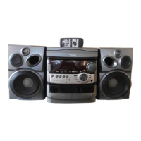
Do you have a question about the Pioneer XR-A330 and is the answer not in the manual?

Pioneer XR-A330 Specifications

General IconGeneral
BrandPioneer
ModelXR-A330
CategoryCassette Player
LanguageEnglish

Summary

Safety and Precautions

Safety Information for Technicians

Information for qualified service technicians regarding safe repair practices.

Product Safety Notice

Highlights components with special safety characteristics and potential hazards.

Laser Safety Precautions

Details on laser interlock mechanism and exposure warnings.

Exploded Views and Parts Lists

Packing Details

Exploded view illustrating packing details for different models.

Exterior Views (1/2)

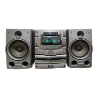
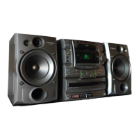
Exploded views illustrating exterior parts (1/2) of the unit.

Exterior Views (2/2)

Exploded views illustrating exterior parts (2/2) of the unit.

Front Panel Section

Exploded view detailing the front panel components.

CD Mechanism and Servo Assemblies

Exploded views and parts lists for the CD mechanism and servo assemblies.

Schematic Diagrams

Overall Wiring Diagram

Overall wiring diagram connecting various assemblies of the unit.

FM/AM Tuner Module Schematic

Schematic diagram of the FM/AM Tuner Module.

CD, Motor, and SW Assemblies Schematics

Schematic diagrams for CD, Motor, and SW assemblies.

AF Assembly Schematics

Schematic diagram of the AF Assembly (part 1/3).

PCB Connection Diagrams

PCB Diagram Viewpoints

Explains the viewing perspective for PCB diagrams.

Tuner Module PCB Layout

PCB layout diagrams for the FM/AM Tuner Module.

CD, Motor, SW, AF PCB Layouts

PCB layouts for CD, Motor, SW, and AF assemblies.

Power Supply and Control Assembly PCB Layouts

PCB layouts for Secondary, Primary, and Sub Trans assemblies.

PCB Parts Lists

Hole PCB Assemblies

Lists PCB assemblies with their corresponding part numbers.

FM/AM Tuner Module Parts

Lists semiconductor, transformer, and other parts for the tuner module.

CD, Display, and AF Assembly Parts

Lists parts for CD, Display, and AF assemblies.

Power Supply and Control Assembly Parts

Lists parts for Primary, Sub Trans, and related assemblies.

Adjustment Procedures

Tuner Section Adjustments

Adjustment procedures for FM and AM tuner sections.

XR-A660 Cassette Deck Adjustment

Mechanical and electrical adjustments for the XR-A660 cassette deck.

XR-A330 Cassette Deck Adjustment

Mechanical and electrical adjustments for the XR-A330 cassette deck.

Test Mode Operations

How to Start/Cancel Test Mode

Instructions on how to enter and exit the test mode for CD operations.

General Information and IC Details

Parts List Overview

Lists general parts and IC details, including schematic references.

IC Pin Functions

Details pin functions for specific ICs like HA12136AF and HA12211NT.

Display Information

FL Display Pin and Grid Assignments

Details on the FL Display, including pin and grid assignments.

Disassembly Instructions

CD Mechanism Disassembly

Illustrated steps for disassembling the CD mechanism.

Front Panel Disassembly

Illustrated steps for front panel disassembly.

Mechanism Component Disassembly

Illustrated steps for disassembling specific mechanism components.

Block Diagram

Overall System Block Diagram

Block diagram illustrating the overall system architecture and signal flow.

Panel Facilities and Specifications

Front Panel Controls Overview

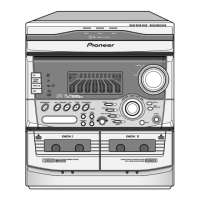
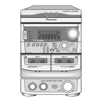
Identifies and describes the front panel controls and indicators.

Display Section Indicators

Explains the meaning of various indicators on the display.

Button Operation Functions

Details the function of common buttons and their behavior across different modes.

System Specifications

Lists technical specifications for the receiver, amplifier, tuner, CD, and cassette sections.

Included Accessories

Lists included accessories such as remote control, antennas, and batteries.

Related product manuals