1.
2.
3.
4.
5.
6.
7.
8.
9.
10.
·11.
12.
13.
14.
15.
16.
17.
18.
19.
20.
2
1.
2 2.
23.
24.
25.
26.
27.
28.
29.
30.
31.
PWER
SENECA
II
SERVICE
MANUAL
CYLINDER
PRESSURE
GAUGE
COMPOUND
GAUGE
VALVE,
LOW
PRESSURE
CONTROL
1
VALVE,VACUUM
CONTROL
2
9
CHARGING
CYLINDER
3
BRACKET
10
SIGHT
GLASS
4
11
19
CYLINDER
BASE
VALVE
HIGH
PRESSURE
GAUGE
12
VALVE,
HIGH
PRESSURE
CONTROL
13
VALVE,
REFRIG.
CONTROL
5
CHAR
GIN
LINE
HOSE
HOLDER
BRACKET
LOW
PRESSURE
CHARGING
LINE
6
14
HIGH
PRESSURE
CHARGING
LINE
HEATING
ELEMENT
PLUG
15
VACUUM
PUMP
7
20
OIL
FILL
LOCATION
8
NECK
ASSEMBLY
16
21
REFRIGERANT
DRUM
SUPPORT
REFRIGERANT
DRUM
VALVE
VACUUM
PUMP
VALVE
VACUUM
PUMP
EXHAUST
PORT
17
TOP
CYLINDER
VALVE
22
REFRIGERANT
DRUM
WEB
STRAP
18
23
REFRIGERANT
DRUM
REDUCER
CHARGING
CYLINDER
HOSE
VACUUM
PUMP
INTAKE
HOSE
VACUUM
PUMP
SWITCH
VACUUM
PUMP
POWER CORD
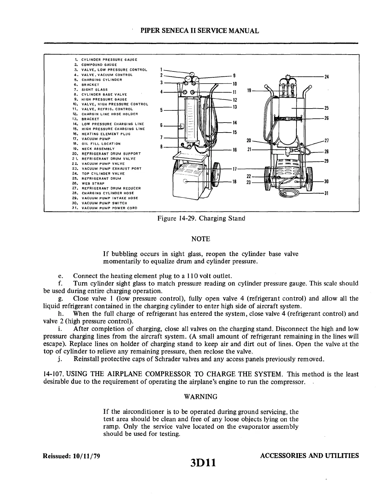
Figure 14-29. Charging Stand
NOTE
-+--+t---25
JIIIE.mE1$11t-f!---26
27
IOl=----.l~---28
~~~~U----29
30
31
If
bubbling occurs in sight glass, reopen the cylinder base
valve
momentarily
to
equalize drum and cylinder pressure.
e. Connect the heating element plug to a 110 volt outlet.
f.
Turn cylinder sight glass
to
match pressure reading on cylinder pressure gauge. This scale should
be used during entire charging operation.
g.
Close
valve
1 (low pressure control), fully open valve 4 (refrigerant control) and allow all the
liquid refrigerant contained in the charging cylinder to enter high side
of
aircraft system.
h. When the full charge
of
refrigerant has entered the system, close valve 4 (refrigerant control) and
valve 2 (high pressure control).
i. After completion
of
charging, close all valves on the charging stand. Disconnect the high and low
pressure charging lines from the aircraft system. (A small amount
of
refrigerant remaining in the lines will
escape). Replace lines on holder
of
charging stand to keep air and dirt
out
of
lines. Open the valve at the
top
of
cylinder to relieve any remaining pressure, then reclose the valve.
j. Reinstall protective caps
of
Schrader valves and any access panels previously removed.
14-107. USING THE AIRPLANE COMPRESSOR TO CHARGE THE SYSTEM. This method
is
the least
desirable due to the requirement
of
operating the airplane's engine
to
run the compressor.
Reissued:
10/11/79
WARNING
If
the airconditioner
is
to
be
operated during ground servicing, the
test area should be clean and free
of
any loose objects lying on the
ramp. Only the service valve located on the evaporator assembly
should be used for testing.
ACCESSORIES
AND
UTILITIES
3D11



 To Next Page