14 - ATR121 - User manual
5.2.b
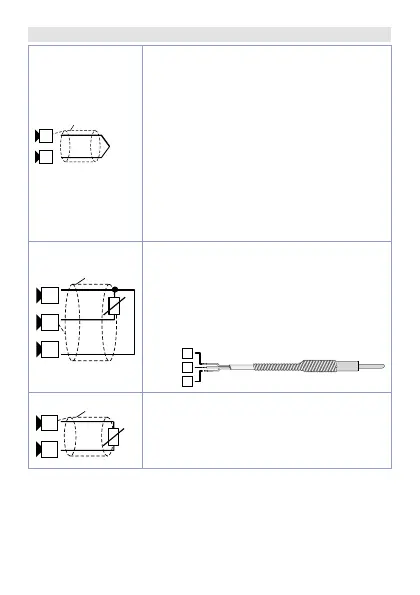
AN1 Analogue Input
-
+
Tc
11 12
Shield/Schermo
For thermocouples K, S, R, J.
• Comply with polarity
• For possible extensions, use
compensated cable and terminals
suitable for the thermocouples
used(compensated)
• When shielded cable is used, it
should be grounded at one side only
(only for models: AD)
For a correct functioning of the device,
use sensors insulated from the ground.
Otherwise, use a single transformer
isolated for each instrument.
10 11 12
PT/NI100
Shield/Schermo
For thermoresistances PT100, NI100
• For the three-wire connection use
wires with the same section
• For the two-wire connection
short-circuit terminals 10 and 12
• When shielded cable is used, it
should be grounded at one side only
Shield/Schermo
PTC/NTC
10 11
For thermoresistances NTC, PTC,
PT500, PT1000 e potentiometers
• When shielded cable is used, it
should be grounded at one side only
to avoid ground loop currents
 Loading...


