User manual - ATR121 - 15
Shield/Schermo
+VDC
9
10 11 12
V/I
+-
For linear signals V/mA
• Comply with polarity
• When shielded cable is used, it
should be grounded at one side only
5.2.c
Examples of connection for linear input
0...10V
1112
For signals 0..10V
• Comply with polarity
PRESSURE TRANSMITTER
SENSORE DI PRESSIONE
0/4...20mA
A
B
C
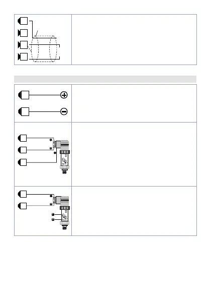
1112 9
For signals 0/4..20mA with three-wire
sensor
• Comply with polarity
C = Sensor output
B = Sensor ground
A = Sensor power supply (12V/30mA)
Versions AD: 12..24Vdc / 30mA
Versions
B: 8Vdc / 20 mA
EXTERNAL SUPPLY
ALIMENTAZIONE ESTERNA
PRESSURE TRANSMITTER
SENSORE DI PRESSIONE
0/4...20mA
B
C
1112
For signals 0/4..20mA with external
power of sensor
• Comply with polarity
C = Sensor output
B = Sensor ground
 Loading...


