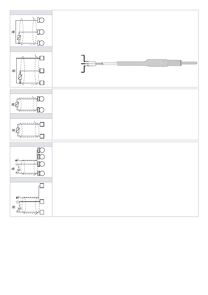
User manual - ATR224 - DRR224 - 11
ATR224-12ABC
For thermoresistances PT100, Ni100.
• For the three-wire connection use wires with the same section.
• For the two-wire connection short-circuit terminals 17 and 19 for ATR224
and terminals 13 and 15 for DRR224.
• When shielded cable is used, it should be grounded at one side only.
RED/ROSSO
WHITE/BIANCO
AI1
PT/NI100
Rosso
Red
Bianco
White
Rosso
19
18
17
DRR224-12ABC
AI1
PT/NI100
Shield/Schermo
Rosso
Red
Bianco
White
Rosso
13
14
15
ATR224-12ABC
For thermoresistances NTC, PTC, PT500, PT1000 and linear potentiome-
ters.
When shielded cable is used, it should be grounded at one side only to avoid
ground loop currents.
AI1
PTC/NTC
17
18
DRR224-12ABC
AI1
PTC/NTC
15
14
ATR224-12ABC
For linear signals in Volt and mA
• Comply with polarity
• When shielded cable is used, it should be grounded at one side only to
avoid ground loop currents.
• It’s possible to select +V at 12Vdc or 24Vdc, by configuring parameter 282
V.out (GROUP R - di SP. - Display and interface).
AI1
V
mA
+V
Shield/Schermo
18
19
DRR224-12ABC
AI1
V
mA
+V
Shield/Schermo
16
14
13