10 - ATR224 - DRR224 - User manual
The controller is designed and conceived to be incorporated into other machines, therefore CE
marking on the controller does not exempt the manufacturer of machines from safety and conformity
requirements applying to the machine itself.
• Wiring of pins 1...8 on ATR224-12ABC: use crimped tube terminals or flexible/rigid copper wire
with diameter 0.2 to 2.5 mm² (min. AWG28, max. AWG12; Minimum temp. rating of the cable to be
connected to the field wiring terminals, 70°C). Cable stripping lenght 7 to 8 mm. Tighten screws to
tightening torque of 0,19 Nm.
• Wiring of pins 9...19 on ATR224-12ABC: use crimped tube terminals or flexible/rigid copper wire
with diameter 0.2 to 1.5 mm² (min. AWG28, max. AWG14; Minimum temp. rating of the cable to be
connected to the field wiring terminals, 70°C). Cable stripping lenght 6 to 7 mm. Tighten screws to
tightening torque of 0,51 Nm.
• Wiring of pins on DRR224-12ABC: use crimped tube terminals or flexible/rigid copper wire with
diameter 0.2 to 2.5 mm² (min. AWG30, max. AWG14, Minimum temperature rating of the cable to
be connected to the field wiring terminals, 70°C). Cable stripping lenght 7 to 8 mm. Tighten screws
to tightening torque of 0,51 Nm.
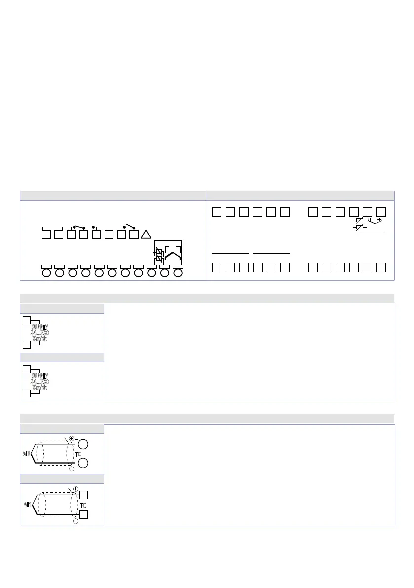
5.1 Wiring diagram
ATR224-12ABC DRR224-12ABC
109 11 12 13
14
19
TC
V/mA
PTC
NTC
PT100
NI100
+V
DO1
(PNP)
DI1
(PNP)
0V
(Rear view)
2A 230V
Resistive
1/8HP
2A 230V
Resistive
1/8HP
24...230V
AC/DC
50/60 Hz
876542 31
+
+
!
24 23 22
24...230V
AC/DC
PT100
TC
NI100 A\V
PTC
NTC
DI1
(PNP)
+V
21 20 19
1
NO C
Q1 Q2
NC NO 0V (PNP)
DO1
C NC
2 3 4 5 6 7 8 9 10 11 12
18 17 16 15 14 13
5.1.a Power Supply
ATR224-12ABC
Switching power supply 24..230 VAC/VDC ±15% 50/60 Hz - (ATR224) and 9
Watt/VA (DRR224).
Galvanic insulation.
SUPPLY
24...230
Vac/dc
1
2
DRR224-12ABC
SUPPLY
24...230
Vac/dc
24
23
5.1.b Analogue Input AI1
ATR224-12ABC
For thermocouples K, S, R, J, T, E, N, B.
• Comply with polarity
• For possible extensions, use compensated cable and terminals suitable for
the thermocouples used (compensated).
• When shielded cable is used, it should be grounded at one side only.
AI1
TC
19
18
DRR224-12ABC
AI1
TC
13
14