12 - ATR224 - DRR224 - User manual
5.1.c Digital input
ATR224-12ABC
Digital input can be enabled by parameters.
Close pin “DI1” on pin
“+V”
to enable digital input.
It is possible to put in parallel the digital inputs of different devices joining
together the pins (0V).
14
DI1
(PNP)
0V
15
16
+V
DRR224-12ABC
DI1
+V
0V
5.1.d Digital output
ATR224-12ABC
Digital output PNP (including SSR) for command or alarm.
Range 12 VDC/25 mA or 24 VDC/15mA selectable by parameter 282
v.out.
Wire the positive control (+) of the solid state relay to the pin DO(x).
Wire the negative control (-) of the solid state relay to the pin 0V.
12
DO1
15
0V
DRR224-12ABC
0V
DO1
9 10
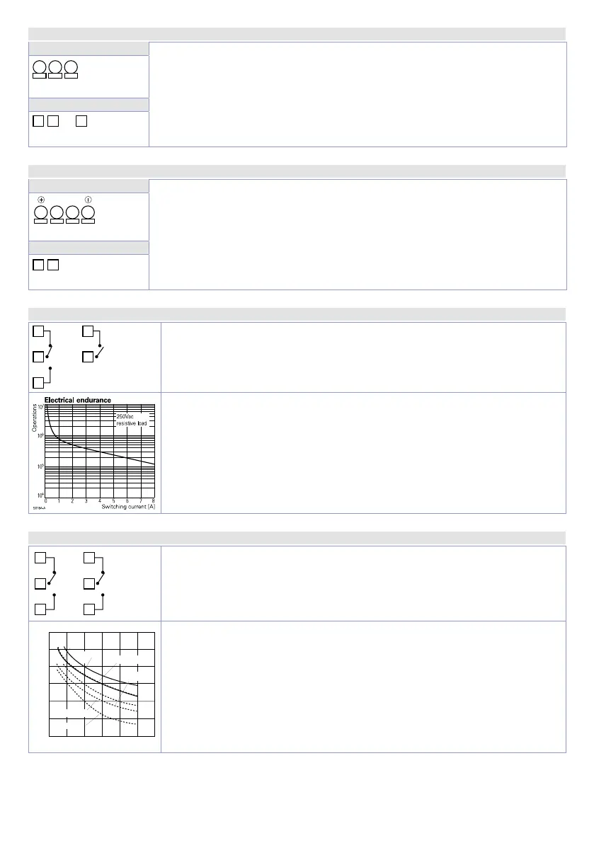
5.1.e Relay output Q1 - Q2 (for ATR224-12ABC)
4
5
Q1
2A 230V
Resistive
1/8 HP
Q2
2A 230V
Resistive
1/8 HP
8
Capacity 2 A / 250 VAC for resistive loads.
See chart below.
Electrical endurance Q1 - Q2:
2 A, 250 VAC, resistive loads, 10
5
operations.
20/2 A, 250 VAC, cosφ = 0.3, 10
5
operations.
5.1.f Relay output Q1 - Q2 (for DRR224-12ABC)
3
2
1
Q1
5A
230V
6
5
4
Q2
5A
230V
Capacity 5 A / 250 VAC for resistive loads.
See chart below.
50
20
10
5
0
1
2 3 4
5
Service life (x10
4
operations)
100
AC125 V
AC125V COS ø=0.4
DC30 V t=7ms
AC250V COS ø=0.4
DC30 V t=15ms
200
AC250V
DC30 V
Electrical endurance Q1 - Q2:
5 A, 250 VAC, resistive loads, 10
5
operations.
20/2 A, 250 VAC, cosφ = 0.3, 10
5
operations.