User manual - ATR224 - DRR224 - 13
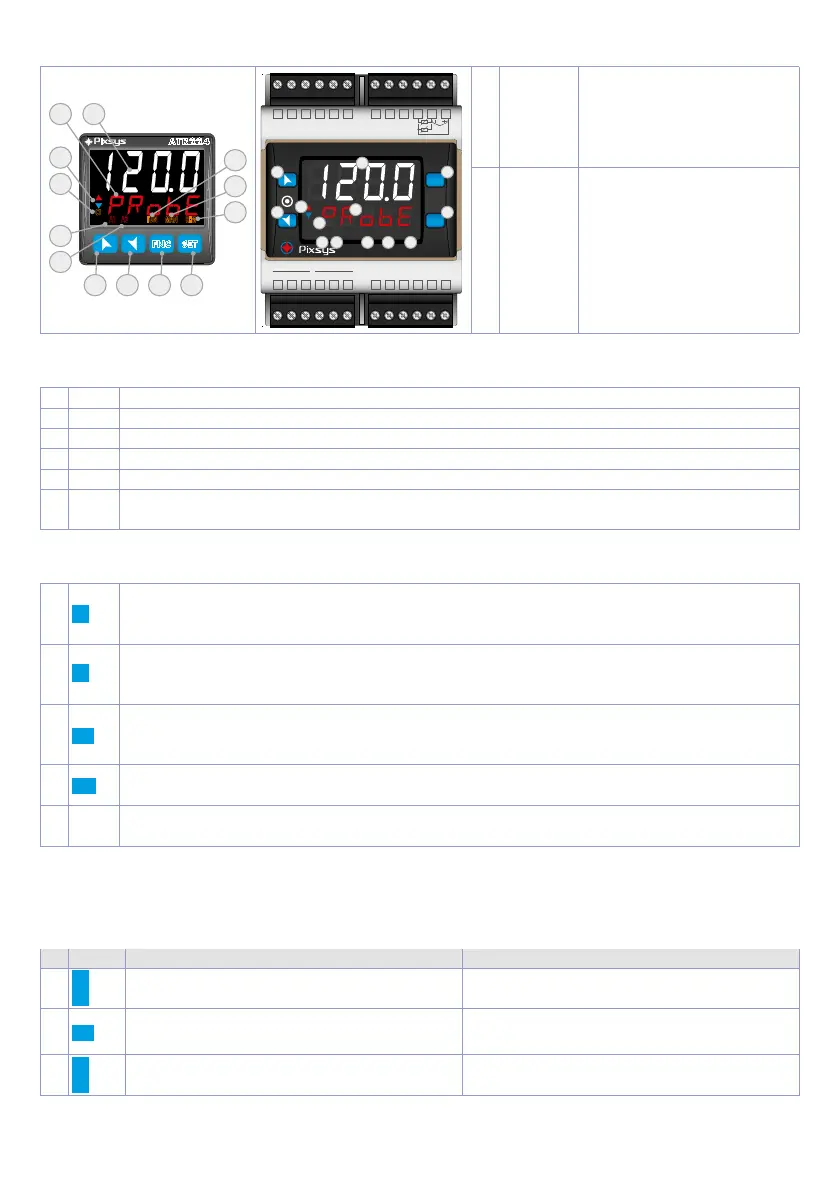
6 Display and Key Functions
FNC SET
ATR224
C1
C2
MAN
TUN
REM
A2A1
A3
3
15
2 1
5
6
11 12 13 14
8
9
10
24 23 22
24...230V
AC/DC
PT100
TC
NI100 A\V
PTC
NTC
DI1
(PNP)
+V
21 20 19
1
NO C
Q1 Q2
NC NO 0V (PN P)
DO1
C NC
2 3 4 5 6 7 8 9 10 11 12
18 17 16 15 14 13
DRR224
FNC
SET
C1
C2 A1 A2 A3 TUN MAN
REM
3
15
2
1
5 6 8 9 10
11
12
13
14
1
123 .4
Normally displays the
process. During the
configuration phase, it
displays the parameter
being inserted.
2
PRo b e
Normally displays the
setpoint. During the
configuration phase, it
displays the parameter
value being inserted.
6.1 Meaning of Status Lights (Led)
3 C1 ON when the command output 1 is active.
5 A1 ON when alarm 1 is active.
6 A2 ON when alarm 2 is active.
8 TUN ON when the controller is executing an auto-tuning cycle.
9 MAN ON when "Manual" function is active.
10 REM
ON when the controller communicates through serial. Flashes when the remote setpoint
is enabled.
6.2 Keys
11
• Increases the main setpoint.
• During configuration allows to scroll the parameters or the groups of parameters.
• Increases the setpoints.
12
• Decreases the main setpoint.
• During configuration allows to scroll the parameters or the groups of parameters.
• Decreases the setpoints.
13
SET
• Allows to visualize command and alarm setpoints.
• During configuration allows to enter the parameter to be modified and confirms the
variation.
14
FNC
• Allows to enter the Tuning launch function, automatic/manual selection.
• During configuration works as exit key (ESCAPE).
15
c
d
• Both ON during parameter modification, when this is not a default value.
7 Controller Functions
7.1 Modification of main and alarm setpoint value
Setpoint value can be modified from keyboard as follows:
Press Display Do
1
Value on display 2 changes.
Increases or decreases the main setpoint
value.
2
SET
Visualizes the other setpoints on display 1.
Display 2 shows the setpoint type.
3
Value on display 1 changes.
Increases or decreases the alarm setpoint
value.