User manual - ATR224 - DRR224 - 15
7.6 Automatic / Manual regulation for % output control
This function allows to switch from automatic functioning to manual command of the output
percentage.
With par. 48
A . m a .1 . (for regulation loop 1) it is possible to select two modes.
1 First selection (
enab.) allows to enable with FNC the writing p.--- on display 1, while on display 2 is
showed
autom.
Press SET to visualize manu.; it’s now possible, during the process visualization, modify through the
keys
c
and
d
the output percentage. To back to automatic, with the same procedure, select autom.
on display 2: immediately led MAN switches off and functioning backs to automatic.
2 Second selection (
en.sto.) enables the same functioning but with two important variants:
• If there is a temporary power failure or after switch-off, the manual functioning as well as the
previous output percentage value will be maintained at restarting.
• If the sensor breaks during automatic functioning, the controller switches to manual mode while
maintaining the output percentage command unchanged as generated by the PID immediately
before breakage.
Ex: on an extruder the command in percentage of the resistance (load) is maintained also in case of
input sensor failure.
7.7 LATCH ON Function
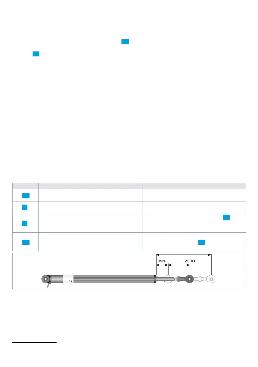
For use with input po t. and with linear input (0..10 V, 0..40 mV, 0/4..20 mA) it is possible to associate start
value of the scale (par. 4
L.L.i .1) to the minimum position of the sensor and value of the scale end (par. 5
u.L.i.1) to the maximum position of the sensor (par. 10 L t c .1 configured as stndr).
It is also possible to fix the point in which the controller will display 0 (however keeping the scale range
between
L.L.i .1 and u.L.i. 1) using the
“virtual zero”
option by selectin u.0.sto. on par. 10 L t c .1 . Selecting
u.0.t.on. the virtual zero must be reset at each switching on; selecting u.0.sto. the virtual zero will remain
fixed once calibrated. To use the LATCH ON function, configure the par.
L t c .1
1
Then refer to the following table for the calibration procedure:
Press Display Do
1
FNC
Exit parameters configuration. Display 2
visualizes writing
La tc.
Place the sensor on minimum operating
value (corresponding to
L.L.i .1)
2
Store value on minimum.
Display shows
Lo w .
Place sensor on maximum operating value
(corresponding to
u.L.i.1).
3
Store value on max.
Display shows
Hi G .
To exit standard proceeding press SET.
For
“virtual zero”
setting, place the sensor to
zero point.
4
FNC
Set virtual zero. Display shows
ero .
If
“Virtual zero at start”
is selected, point 4
must be repeated at each starting.
To exit procedure press SET.
1 The tuning procedure starts by exiting the confi guration after changing the parameter.