32
Ingresso analogico
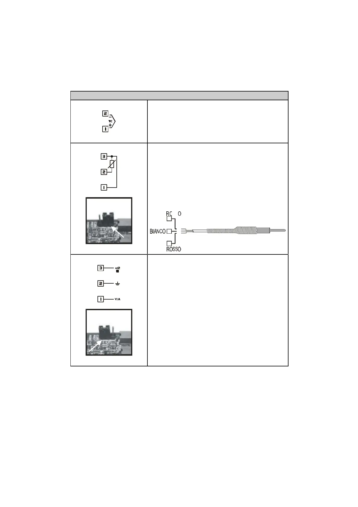
4. Per termocoppie K, S, R, J
• Rispettare la polarità
• Per eventuali prolunghe utilizzare cavo
compensato e morsetti adatti alla
termocoppia utilizzata (compensati)
5. Per termoresistenze PT100, NI100
• Per il collegamento con sonde a tre fili
usare cavi della stessa sezione
• Per collegamento con sonde a due fili
cortocircuitare morsetti 1 e 3
• Selezione il jumper interno JP3 come
in figura
1
2
3
6. Per segnali normalizzati in corrente
e tensione
• Rispettare la polarità
• Selezione il jumper interno JP3 come
in figura.
In caso contrario non saranno
disponibili i 12Vdc sul morsetto
numero 3 per l’alimentazione del
sensore.