8
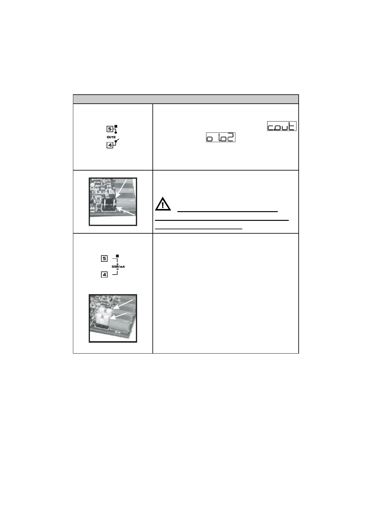
Output Out2 : Relay / SSR / 4…20mA
Contacts capacity 3A/250V~ resistive
Operating with available configurations:
• Alarm relay with parameter 1
selected as
• Valve-closing relay with configuration
Open/Close
• To select Out2 as relay output, remove
jumpers JP5 and JP7 as in the picture
Connecting the load without
removing jumpers will lead to serious
damage of the controller
Capacity 12V/30mA
• Control output with configuration SSR
• Alarm 1 with command on OUT1
• Output 4-20mA configurable by
parameters as control or for
retransmission of process or setpoint
value
• Select JP5 and JP7 as in the picture
(place both of them) to get SSR
output or 4-20mA output