6
2.Insert positive/negative DC power wires into Contacts 1 and 2 for Power 1,
or Contacts 5 and 6 for Power 2.
DC48-54V(IGS-6325-4UP2X)
DI1 DO0 DO1DI0 GNDGND
DC Input:
48-54V , 8.3A max.
Dual power input is required
for maximum PoE loading.
Refer to user’s manual for
more details.
PWR1 Alarm PWR2
V1+
V2+
Max. Fault Alarm Loading: 24V, 1A
1 2 3 4 5 6
1 2 3 4 5 6
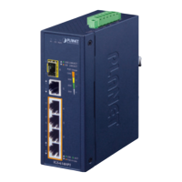
Figure 3-2: IGS-6325-4UP2X Upper Panel
IGS-6325-4UP2X
DCInputVoltage 48-54VDC
Max. DC Input Current 8.3A
PWR1 and PWR2 must provide exactly the same DC voltage
for power load balance while operating with dual power input.
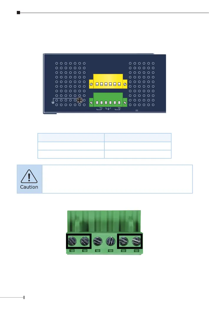
3.Tightenthewire-clampscrewsforpreventingthewiresfromloosening.
1 2 3 4 5 6
V1+ V1- V2+ V2-
Power 1 Power 2
Figure 3-3: Power 1 & 2 Pins of Terminal Block Connector
 Loading...