5
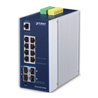
3. Wiring the Power Inputs
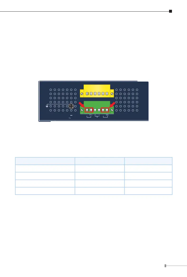
The Upper Panel of the Industrial Managed Switch indicates an inlet power
socket and consists of one green terminal block connector with 6 contacts.
Please follow the steps below to insert the power wire.
1.Insert positive/negative DC power wires into Contacts 1 and 2 for Power 1,
or Contacts 5 and 6 for Power 2.
DC9-48V,AC24V(IGS-6325-4T2X&IGS-6325-5X1T)
Max. Fault Alarm Loading: 24V, 1A
DI1 DO0 DO1DI0 GNDGND
V1+ V2+
PWR1
PWR2Alarm
DC Input: 9-48V
, 4A max.
AC Input: 24V
, 2A max.
1 2 3 4 5 6
1 2 3 4 5 6
Figure 3-1: IGS-6325-5X1T Upper Panel
(Wiring methods also apply to IGS-6325-4T2X except dierent max. input current values)
Refer to the table below for the Input Voltage and Current Values for each
model
IGS-6325-4T2X IGS-6325-5X1T
DCInputVoltage 9-48VDC 9-48VDC
Max. DC Input Current 3A 4A
ACInputVoltage 24VAC 24VAC
Max.ACInputCurrent 1.5A 2A