5
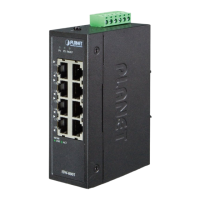
3. Wiring the Power Inputs
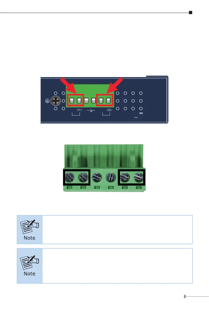
The Upper Panel of the Industrial Managed Switch indicates a DC inlet
power socket and consists of one terminal block connector within 6 contacts.
Please follow the steps below to insert the power wire.
1. Insert positive/negative DC power wires into Contacts 1 and 2 for POWER 1,
or 5 and 6 for POWER 2.
V1+ V2+
PWR1
PWR2Fault
DC Input: 12-48V
, 1.2A max.
AC Input: 24V
, 1.1A max.
Max. fault loading: 24V, 1A
1 2 3 4 5 6
2. Tighten the wire-clamp screws for preventing the wires from loosening.
1 2 3 4 5 6
Power 1 Power 2
+ - + -
The wire gauge for the terminal block should be in the range
between 12 and 24 AWG.
1. The power input range is 12V
~
48V DC and supports 24V
AC.
2. Use one power input when using 24V AC.