17
2.1.2 LRP-101CH Front Panel and Rear Panel
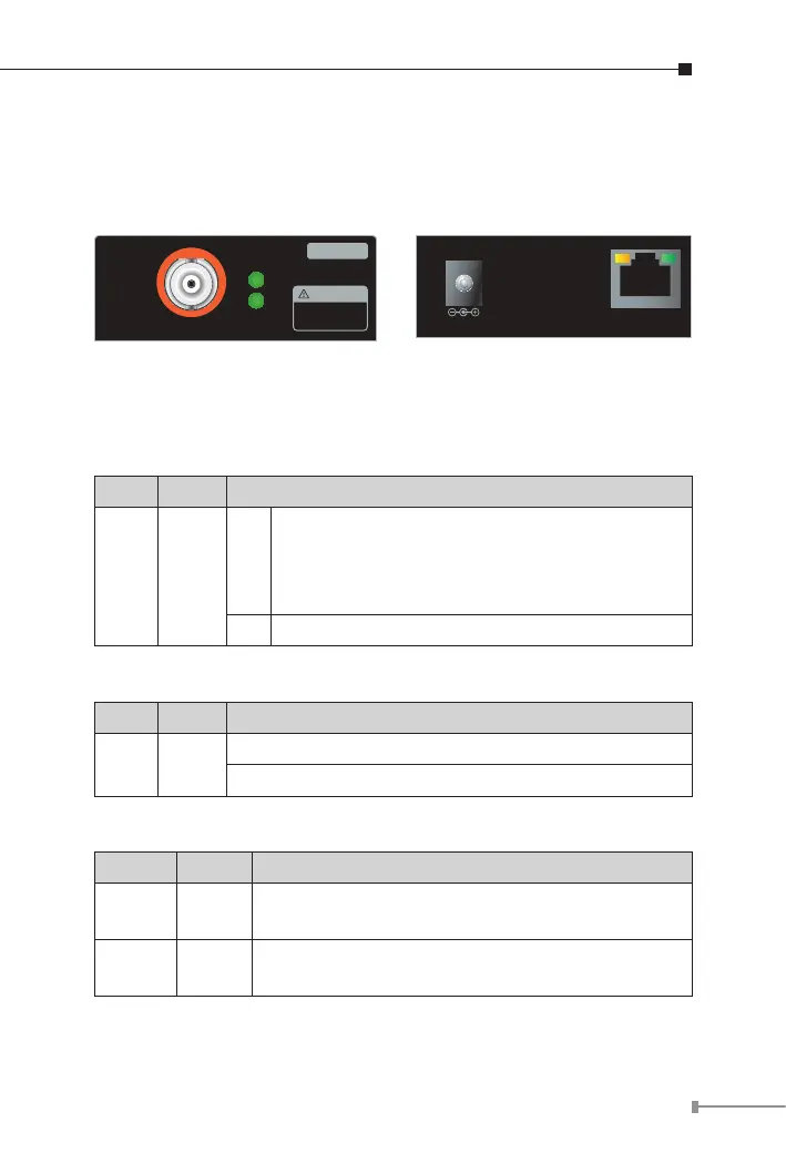
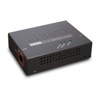
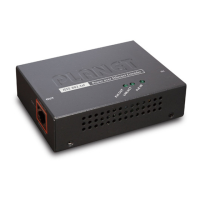
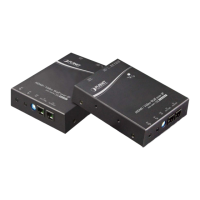
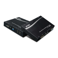
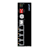
Figure 2-1 and Figure 2-2 show the front and rear panels of the
LRP-101CH Long Reach PoE over Coaxial Injector.
48~56V DC IN
LNK/ACTPoE IN
10/100BASE-TX
LRP-101CH
LNK
PWR
LRP OUT
Injector
Long Reach PoE Injector - Coax
The LRP interface is
allowed to connect to
LRP Extender only.
CAUTION
Figure 2-1: LRP-101CH Front Panel Figure 2-2: LRP-101CH Rear Panel
2.1.3 LRP-101CH LED Indicators
System
LED Color Function
PWR Green
Lit
Power ON: PoE+ / PoE power input from RJ45
PoE PD port
Power ON: 48~56V DC power input from DC
jack
Off Power Off
LRP Coaxial Interface
LED Color Function
LNK Green
Lit: indicates that the coaxial link is established.
Off: indicates that the coaxial link is down.
RJ45 10/100BASE-TX Interface
LED Color Function
PoE IN Amber
Lit: indicates the RJ45 port is receiving the PoE
Power.
LNK/
ACT
Green
Blink: indicates the extender is actively sending or
receiving data over that port.