REP 2.13 Adjustment of Eject motor M4
T08009 TJ
PURPOSE
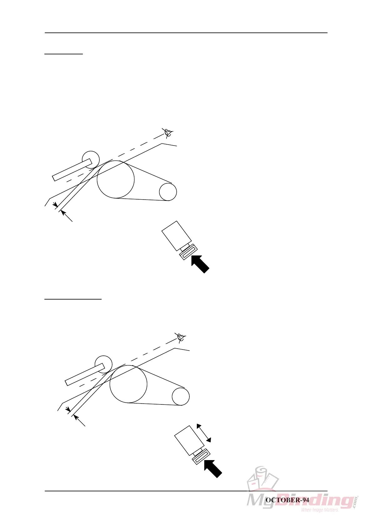
There should be a clearance between the Idler roller and the Eject feed wheel when Solenoid SOL1
is activated. If Idler roller and Feed wheel are touching there could be a problem to feed sets with
large sizes (A3/11"x17").
1. Switch off the main power switch and disconnect the power cord.
2. Remove Infeed cover, CRI 1.2.
3. Press on the plunger for Solenoid SOL1 and view from the infeed side, the rollers will appear to
be
flush when there is a 2mm space in between them.
2 mm
SOL1
ADJUSTMENT
1. Loosen the screw on the rear side of Solenoid SOL1 and position the solenoid to obtain the correct
distance between the rollers.
2 mm
SOL1
STAPLER FOLDER MODEL 60/61 PAGE 2.13 OCTOBER-94
 Loading...


