△
1211
CT1
C
B
A
c
b
10 9 8
7
6 5
4
3
2
19
20
21
CT2
a
31302928
27
2625
24
23
22
FG
1
A
B
RS-485
C1
、
ub ua
uc
13
14
15
16
17
18
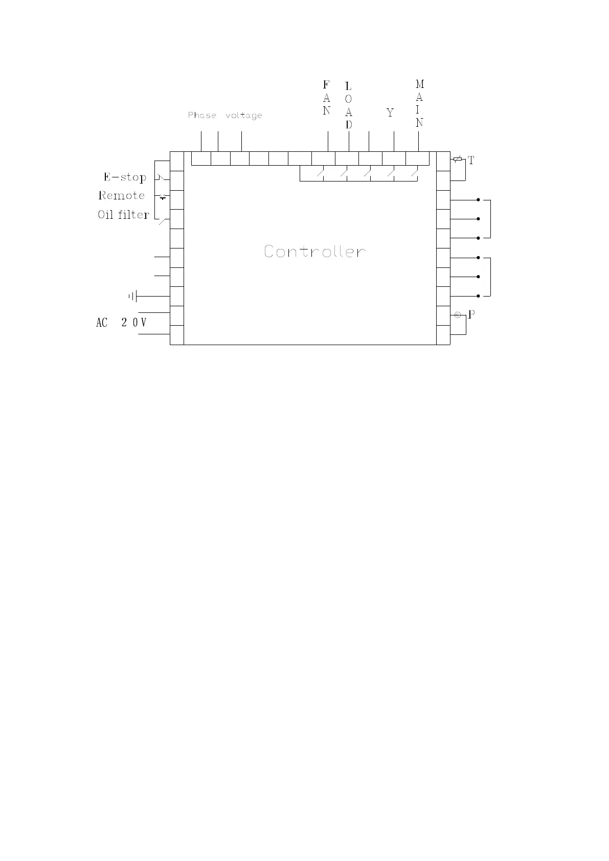
Figure 4.2.1 Terminal arrangement diagram
Terminal blocks of controller:
1 is common terminal COM1;2 is input terminal for emergent stop signal; 3 is remotely controlled for
on/off signal input terminal;4 terminal is used to detect oil filter blocked; 6 is RS485 A; 7 is RS485 B;8 is the
simulated ground (Earth);17 and 18 are the AC20V power source;22、23 terminals are Pressure Sensor signal
input;24、25、26 terminals are motor mutual inductor CT1 input;27、28、2 terminals are Fan mutual inductor
CT2 input;30、31 terminals are Temperature Sensor signal input;19、20、21 terminals Used to detect the phase
sequence and voltage;13 terminals is common terminal of output relay;14 terminals controls fan;15 terminals
controls load valve;16 terminals controls angle-shaped contactor;17 terminals controls star-shaped contactor;
18 terminals controls main contactor。
NOTE: Eelectromagnetism coil shall be connected with surge absorber during wiring, and
dotted lines are extendable functions.
5、 Control principles
1、Local Automatic control
①. press down start button for starting: (Y-△start)
There is fives of self-test after controller is energized and it can not be started by pressing start
button .The air compressor starts by pressing start button after self-test finished. The course of
compressor’s start as followed: KM3 and KM2 are energized → Y-type status of start → delay time is
reached (Y-△change-over time); KM3 is de-energized (KM1 and KM3 are interlocked) and KM1 is
energized → motor operates with △ type to finish start. During the course of starting, all
electromagnetism valves are de-energized to achieve no load start.
②. Automatic operation control:
When the motor is started to running in △ status and load the magnetic valve with