Rel. 03
14
Verify that the section of the feeding wire is able to support the power that the machine uses up in
full load. For greater safety, the wire must be protected from involuntary crushing by a raceway or
an anti-crushing sheathing.
Before beginning the work, verify that the rotation direction of the spindles corresponds to
the direction of the pointer applied to the drilling units. In case the spindles rotate in
opposite direction, you must reverse two phases in the line connection.
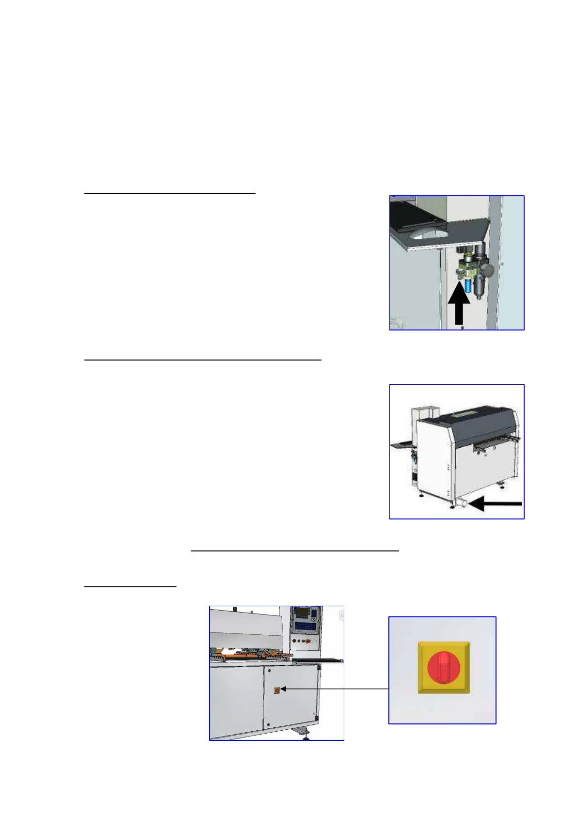
4.5 AIR CONNECTION INSTRUCTIONS
Connect the machine to the air feeder using a tube with an inside
diameter of 10mm.
Connect the FRL group to the air piping. The group has a ½” Gas
(UNI – 339-66) threaded feeding hole. The minimum line pressure
must be of 0.8 MPa. This is necessary to guarantee a fast response
of the air cylinders and to avoid, during operation, a drop of the
pressure under 0.6 MPa.
4.6 INSTRUCTIONS CONNECTING INTAKE SYSTEM
Connect the intake system, the connection shown in the figure. Use
a tube inside diameter 120mm.
CAP. 5 CONTROL AND SAFETY DEVICES
5.1 COTROL DEVICES
- Main switch