2 - 10 SUSPENSION AND STEERING
GEM Service Manual November 2007
REMOVAL
REAR HUB AND
BEARING/SPINDLE
(6 PASSENGER & LONG
BACK EXTRA DUTY)
(e6, e6S, eLXD)
1. Raise and support the vehicle on a suitable
hoist.
2. Remove the hubcap.
3. Remove the tire and wheel assembly.
4. Remove the brake drum.
5. Remove the bearing dust cap
6. Remove the hub bearing retainer.
7. Remove the rear hub and bearing.
8. Remove
the bolts and rear spindle.
NOTE: Support the backing plate assemblies to
protect the brake lines and parking brake
cables.
INSTALLATION
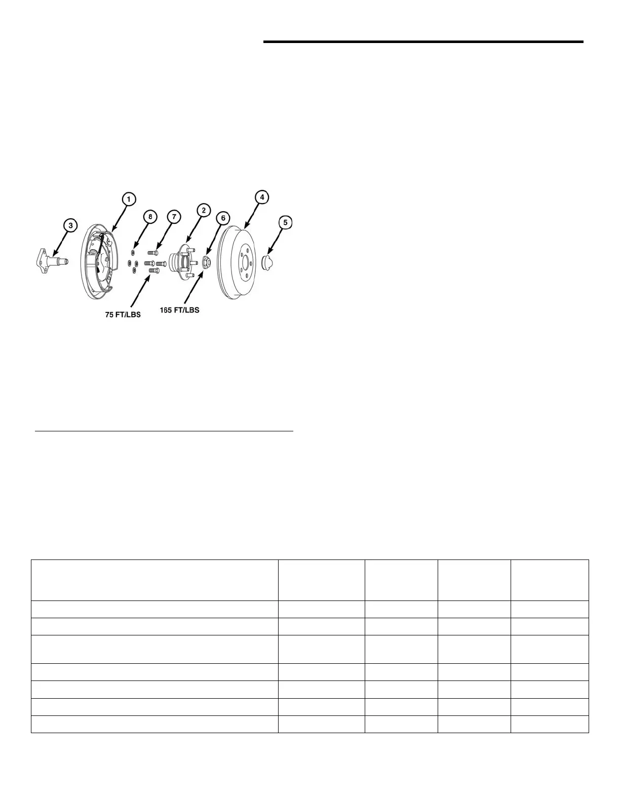
1. Install bolts for the backing plate and rear
spindle. Note: Apply thread sealer to spindle
bolts. Tighten bolts to 75 ft-lbs.
Fig. 7 Rear Hub and Bearing/Spindle
2. Install the rear hub and bearing. Tighten
1 - Assy. Brake - LH Rear
2 - Assy. Hub - Rear
3. Install the hub and bearing. Torque to
165 ft-lbs.
3 - Spindle - Rear
4 - Drum 5 - Bolt
4. Install the dust cap.
5 - Dust Cover
6 - Hex Nut
5. Install the brake drum.
7 - Hex Bolt
6. Install the tire and wheel assembly. Tighten just
snug.
8 - Lock Washer
7. Tighten the lug nuts to 65 ft-lbs.
8. Install the hubcap.
9. Lower the vehicle to the floor.
10. Tighten the rear suspension to frame bolts to
60 ft-lbs.
11. Tighten the spring/shock absorber bolts to
60 ft-lbs.
TORQUE SPECIFICATIONS
Description Thread Size Use
Loctite®
242
Inch-
Pounds
Foot-
Pounds
Brake line to wheel/master cylinder
NO 37 ---
Brake, drum assembly to rear axle
M8 x 1.25 NO --- 19
Brake, parking – cable mount to rear
suspension
½” x 13 NO --- 50
Rear suspension frame to frame
M12 x 1.75 NO --- 60
Shock absorber lower bolt
M12 x 1.75 NO --- 60
Shock absorber upper bolt
M12 x 1.75 NO --- 60
Wheel lug nuts
12mm NO --- 65
 Loading...