ELECTRICAL 5 - 32
November 2007 GEM Service Manual
MOTOR CONTROLLER
DESCRIPTION
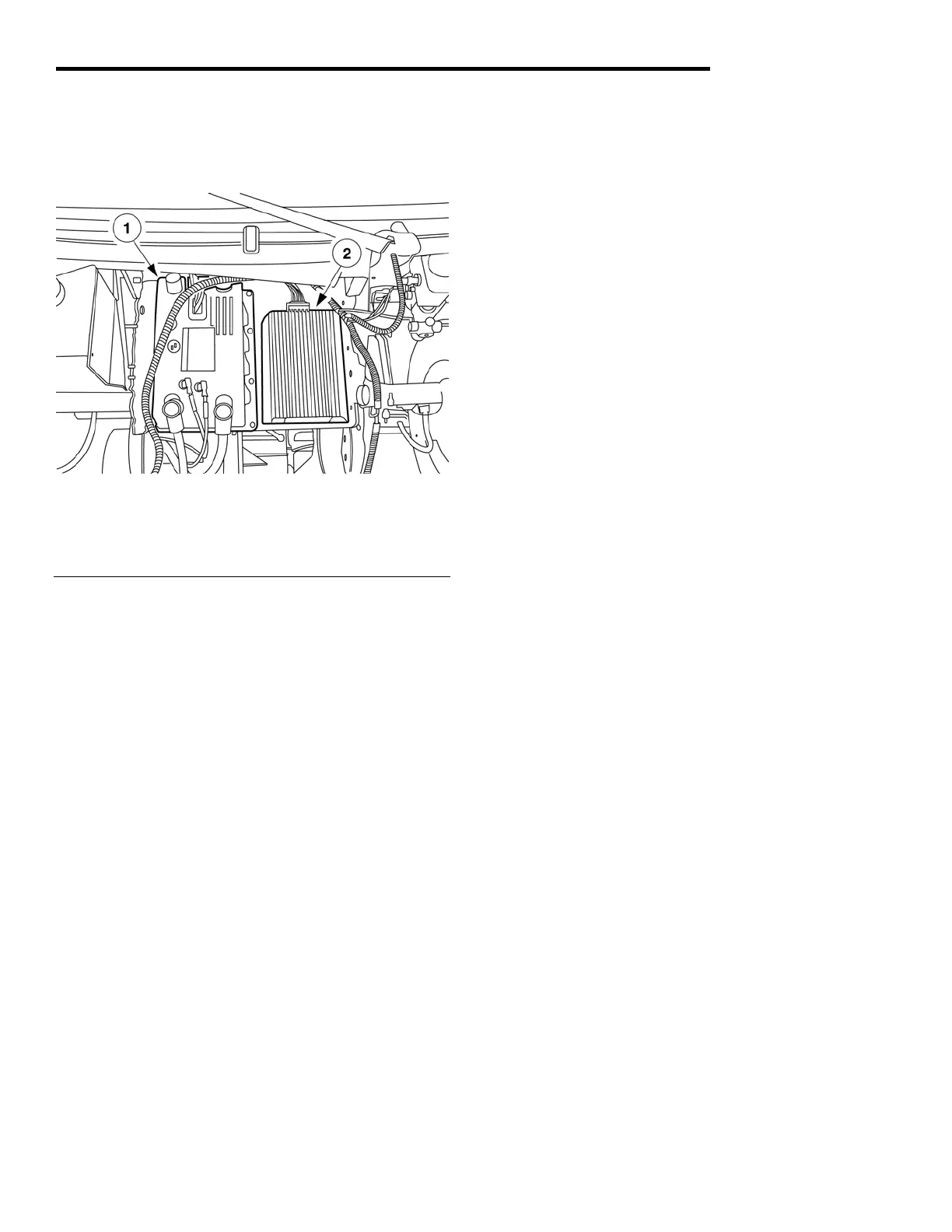
Fig. 16 Motor Controller
1 - Motor Controller
2 - DC/DC Converter
The motor controller, located under the hood
assembly, is the brain of the GEM vehicle. Based
on inputs from the accelerator pedal and the drive
mode switch, the controller converts battery power
into the appropriate drive power for the vehicle's
electric motor. The controller also generates drive
system status information that is displayed on the
liquid crystal display (LCD).
OPERATION
The controller functions automatically when the
master disconnect switch is in the ON position.
There are no other direct operator interactions with
the motor controller module. Operation of the motor
controller is accomplished by actuation of the
devices such as the accelerator pedal, and the
drive mode switch.
DIAGNOSIS AND TESTING
The motor controller function is critical to every
aspect of the drive system. If a fault occurs with the
motor controller, you should see an error code on
the liquid crystal display (LCD). Use the Drive and
Power System Error Codes section starting on
page 5-6 Electrical to help in isolating the fault.
REMOVAL
1. Turn the master disconnect switch OFF.
2. Open the hood assembly.
3. Disconnect all cables and connectors, noting
connection location and wire orientation.
4. Remove bolts holding controller to bracket.
INSTALLATION
1. Install the controller in place, install and tighten
bolts holding controller to bracket. Torque to
50 in-lbs.
2. Connect all cables and connectors, noting
connection location and wire orientation.
3. Close the hood assembly.
4. Turn the master disconnect switch ON.