ELECTRICAL 5 - 42
November 2007 GEM Service Manual
The standard accessory system components for
the GEM are essential for safe driving and consist
of the headlights, taillights, directional indicators,
and brake lights, horn, and wiper. Some vehicles
are equipped with a radio, light bar, power outlet
and heater that are considered optional equipment.
OPERATION
Standard accessories receive their 12-volt power
from the fuse protected DC/DC converter. The
DC/DC converter receives 72-volt input power
directly from the six batteries and requires no user
action for its operation. All other components of the
Accessory System function identical to those
devices in a standard automobile.
The two headlights are 12-volt single filament
incandescent bulbs. A rocker switch located on the
instrument pod activates headlights. (High/Low
beam headlights optional.)
Taillights and brake lights are 12-volt dual filament
incandescent bulbs. One filament is used for
directional indicators and brake lights. The second
taillight filament is activated when the headlights
are turned on.
There are 4 directional indicators, left and right
front, and left and right rear. Turn signal lever
located on the left side of the instrument pod
activates the directional indicators. The turn signal
indicator has a built-in time delay relay and buzzer
set for 45 seconds as a reminder. As the turn
indicators are selected and not switched off within
the 45-second period a small beeping sound will
omit as a reminder to switch the turn signals off.
The horn provides a single continuous tone when
the horn button is pressed. The horn button is
located on the left side of the instrument pod.
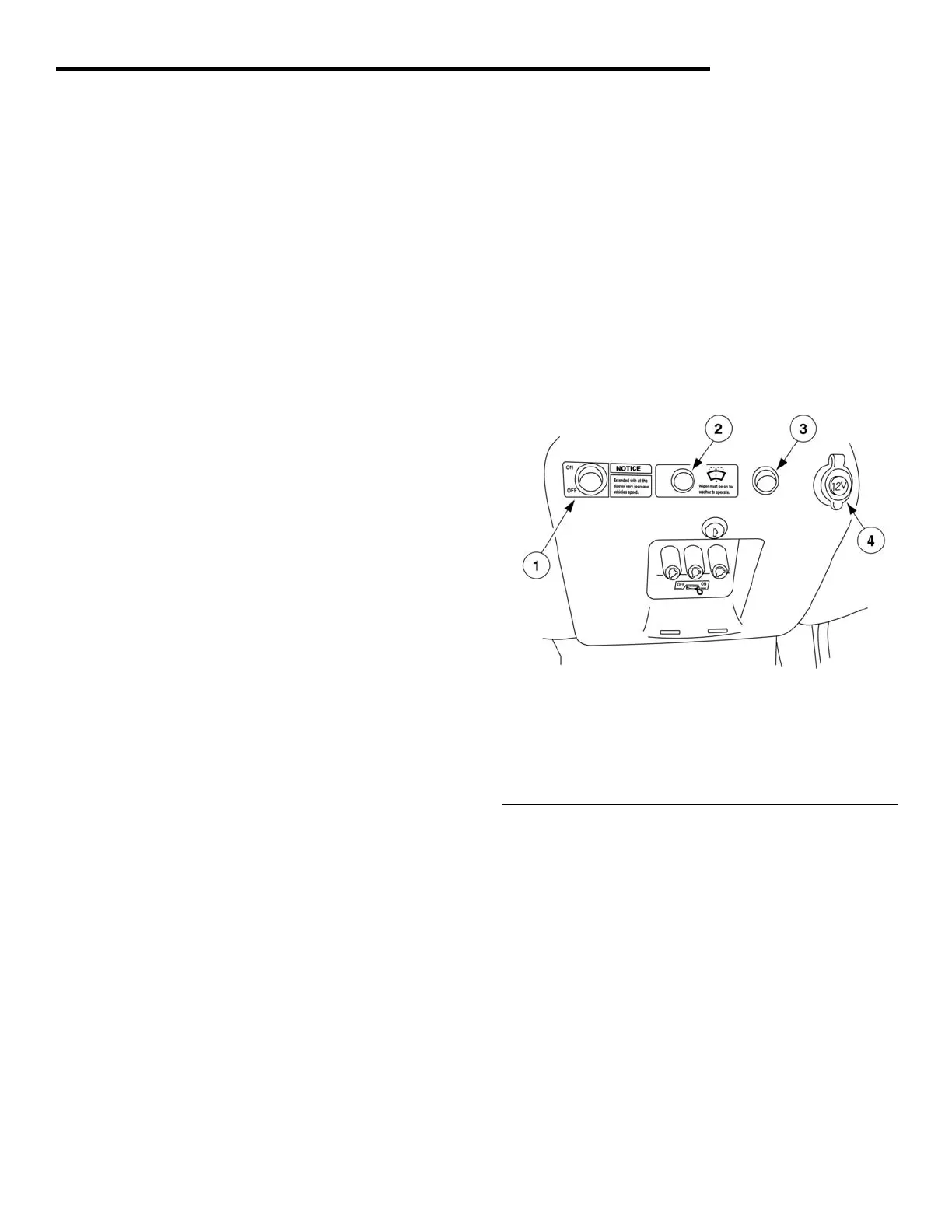
The heater operates by the heater switch located in
the center lower dash panel (figure 27 item 1). The
heater blower motor operates by receiving 12 VDC
from the fuse protected DC/DC converter. The
heater element runs on 72 VDC fused direct feed
from the batteries through the heater contactor.
The light bar operates by the light bar switch
located in the center lower dash (see figure 27 item
3). The light bar is powered by receiving 12 VDC
from the fuse protected DC/DC converter.
The power outlet is located in the center lower dash
(see figure 27 item 4) and is running on 12 VDC
from the fuse protected DC/DC converter.
The radio is located in the headliner and is running
on 12 VDC from the fuse protected DC/DC
converter.
A single speed DC motor powers the wiper. The
motor automatically returns the wiper to the Parked
position when the wiper is turned off. A lever
switch, the windshield wiper (see figure 27 item 2)
on the left side of the instrument pod activates the
wiper.
Fig. 27 Center Lower Dash
1 - Heater Switch
2 - Windshield Washer Switch
3 - Light Bar Switch
4 - Power Outlet
DIAGNOSIS AND TESTING
The purpose of this section is to aid in the isolation
of problems with the accessory system. Unlike the
drive system, the LCD does not provide any error
codes to aid in troubleshooting problems with
accessories. The most common problems with the
accessory system are an open lamp filament, a
faulty switch, improper wiring connections and
blown fuses. For problems that cannot be resolved
by lamp and fuse replacement, refer to the
Accessory System Troubleshooting Chart and the
wiring diagrams provided.