3 - 2 DRIVETRAIN
GEM Service Manual November 2007
When turning corners, the outside wheel must
travel a greater distance than the inside wheel to
complete a turn. The difference must be
compensated for to prevent the tires from scuffing
and skidding through turns. To accomplish this, the
differential allows the axle shafts to turn at unequal
speeds.
DRIVETRAIN
DESCRIPTION
The drivetrain consists of a 72-volt motor, a
gearbox/differential and two constant velocity drive
shafts called halfshafts.
HALFSHAFT
DESCRIPTION
The halfshaft assembly consists of a shaft with
rubber boots at each end for protection from dirt,
etc. A splined socket on the inboard end of the
shaft mates with a splined shaft on the differential.
The splines on the outboard end of the halfshaft
mate with the splines in the front wheel spindle
assembly.
OPERATION
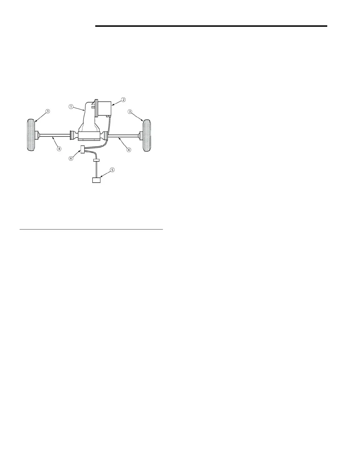
Fig. 1 Drivetrain
Rotating motion of differential side gear is
transferred to front wheel spindle by the halfshaft.
1 - Differential 4 - Half Shaft
2 - Motor 5 - Accelerator
3 - Wheel 6 - Controller
DIAGNOSIS
Halfshafts must be replaced if they exhibit any of
the following symptoms.
OPERATION
• A clicking noise in turns, which indicates that
the outboard joint is damaged.
Batteries power the motor. The accelerator pedal
(potentiometer) controls the motor speed. The
motor is connected to a differential. The power is
transferred from the differential through two
constant velocity (CV) drive shafts (halfshaft) to
the wheel hubs.
• A thump or clunk when accelerating from
coasting, which points to a faulty inboard joint.
• Vibration or shuddering during acceleration,
which may be caused by a damaged inboard
or outboard joint, a sticking inboard joint, or an
excessive operating angle.
The halfshaft must be replaced as an assembly if
the CV boots exhibit grease accumulating around
the outside of the boot. This is caused either by a
small hole or a tear in the boot.
NOTE: For instructions on motor and
accelerator replacement/repair, see section 7.
During straight-ahead driving, the differential
pinion gears do not rotate on the pinion mate shaft.
This occurs because input torque applied to the
gears is divided and distributed equally between
the two side gears.
REMOVAL
1. Switch master disconnect switch to OFF.
2. Raise and support vehicle on a suitable hoist.
3. Remove hubcap.
4. Remove front tire and wheel assembly.
5. Remove cotter pin and nut from outboard end
of halfshaft with 15/16-inch socket.
6. Remove upper bolt from front shock.
 Loading...